Caution – Rockwell Automation 140U K-Frame CB Alarm Switch and Alarm /Auxiliary Switch Combination User Manual
Page 6
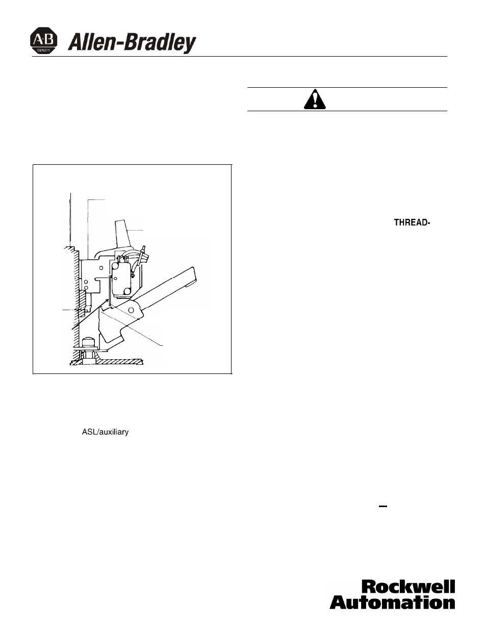
c. Slide accessory combination mounting bracket
into slots until retaining clip snaps into trip unit.
Be sure that auxiliary switch operating arm is
between accessory operating projection on the
molded crossbar and arc extinguisher
(Fig. 2-8). For terminal block assemblies, slide
terminal block into mounting slot on side of
base as accessory combination is being posi-
tioned.
Ctip
r
Breaker
Handle
Fig. 2-8. Auxiliary Switch Operating Arm Location
d. If required, complete routing of leads to oppo-
site-side through rear wiring trough.
e. For
switch accessory combina-
tion with pigtail leads, attach wire marking
labels
to bundle of three leads for each switch.
(Markers designated A and B are provided.)
General Installation
CAUTION
WHEN INSTALLING CIRCUIT BREAKER COVER,
MAKE SURE THAT ALL INTERNAL PARTS ARE IN
PLACE:
. SLIDING HANDLE BARRIERS ARE INSTALLED
SO THAT THE HANDLE OPENING IS ALIGNED
WITH THE HANDLE.
l
PIGTAIL LEADS ARE CLEAR OF COVER.
WHEN REMOVED AND REINSTALLED,
FORMING SCREWS TRY TO REFORM THE THREADS
IN THE CIRCUIT BREAKER BASE. CARE SHOULD
BE TAKEN EVERY TIME A THREAD-FORMING
SCREW IS USED TO ENSURE THAT THE SCREW
STARTS IN THE ORIGINAL THREADS. DAMAGED
THREADS CAN RESULT IN IMPROPER CIRCUIT
BREAKER COVER RETENTION.
2-14. With circuit breaker handle in TRIPPED position
and accessory pigtail leads (if used) routed as
required, install circuit breaker cover. Secure with
pan-head screws followed by thread-forming
screws, as shown in Fig. 2-10.
2-15. Place accessory labels (supplied with kit) on circuit
breaker. (See Fig. 2-11.)
Note: Accessory labels show connection diagram for
ASL switch and/or auxiliary switch contacts. Pigtail
leads are color coded red, black, and blue. Be sure
that wire marking label is attached correctly to leads
and agrees with related leads at accessory.
2-16. Test ASL switch by connecting continuity tester or
ohmmeter across pigtail leads or terminal block
connections. Check continuity as follows:
a.
Circuit breaker handle OFF
Check that
make contact(s) are open and break contact(s)
are closed.
40752-035(1)
Effective 3/02
Page 6
Trip Unit
Auxiliary Switch
Mounting Bracket
Accessory Operating
g
Projection
Auxiliary Switch
Operating Arm