Rockwell Automation 25B PowerFlex 520-Series EMC Filter User Manual
Powerflex 520-series emc filter installation, Installation instructions
Publication 520-IN006B-EN-P - September 2013
Installation Instructions
PowerFlex 520-Series EMC Filter Installation
Catalog Numbers: 25-RF011-AL, 25-RF023-BL, 25-RF014-AL, 25-RF021-BL, 25-RF027-CL, 25-RF035-DL, 25-RF056-EL, 25-
RF7P5-AL, 25-RF014-BL, 25-RF018-CL, 25-RF033-DL, 25-RF039-EL, 25-RF8P0-BL, 25-RF014-CL, 25-RF027-DL, 25-RF029-EL
pl: numbers ok
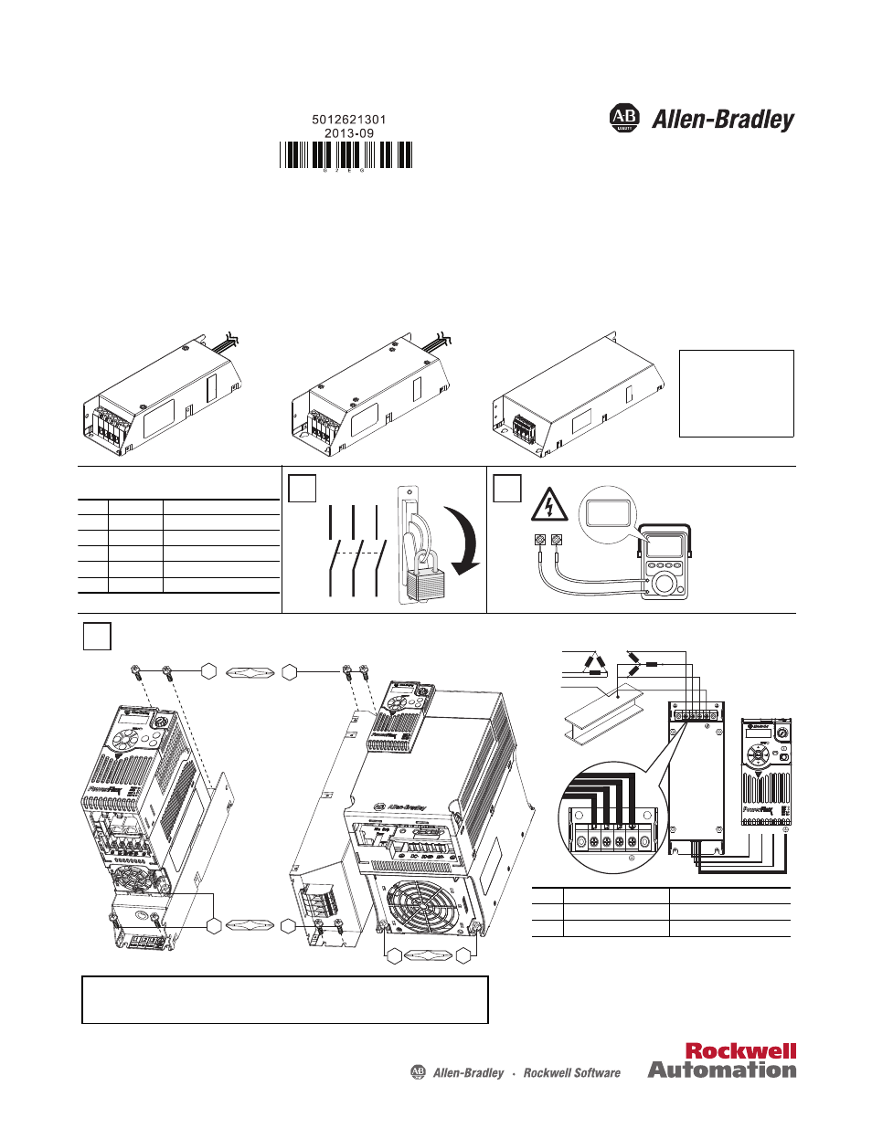
Frame A Filter
25-RFxxx-AL
Frame B...D Filter
25-RFxxx-BL
25-RFxxx-CL
25-RFxxx-DL
Frame E Filter
25-RFxxx-EL
Note: The drive side for all
frame A...D filters is
prewired with three or
four wires depending on
number of phases.
L1
L2
L3
O
I
DC+ DC–
0V
0V
Wait three minutes
after shutdown for
capacitors to discharge
to safe voltage levels.
Filter Mounting
Frame Screw Size
Screw Torque
A
M5 (#10...24) 1.56...1.96 Nm (14...17 lb-in)
B
M5 (#10...24) 1.56...1.96 Nm (14...17 lb-in)
C
M5 (#10...24) 1.56...1.96 Nm (14...17 lb-in)
D
M5 (#10...24) 2.45...2.94 Nm (21.7...26 lb-in)
E
M5 (#10...24) 1.56...1.96 Nm (14...17 lb-in)
2
1
M5
M5
M5
5.98...7.34 Nm
M8
M8
M5
53...65 lb-in
3
For Frame A...D
For Frame E
Frame Wire Gauge
Screw Torque
A...D
0.32...8.4 mm
2
(22...8 AWG) 1.59...1.94 Nm (14.1...17.2 lb-in)
E
2.1...26.7 mm
2
(14...3 AWG) 3.09...3.77 Nm (27.3...33.4 lb-in)
ATTENTION:
Mount the EMC Filter to the Drive
Filter Terminal Wiring
R/L1 S/L2 T/L3
R/L1 S/L2 T/L3
R/L1 S/L2 T/L3
• All Frame E filters must be mounted on its side.
• 600V Frame A drives can be mounted on Frame B filters.