Rockwell Automation 160 FRN 5-6.XX Quick Reference Card User Manual
Page 3
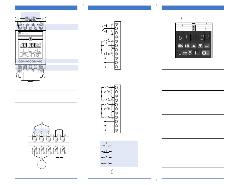
Control Wiring – TB3
Power Wiring – TB1, TB2
Fault Codes
Fault
No.
Fault Indication and Corrective Action
03
Power Loss Fault
Monitor incoming AC line for low voltage or line power
interruption.
04
UnderVoltage Fault
Monitor incoming AC line for low voltage or line power
interruption.
05
OverVoltage Fault
Bus overvoltage caused by motor regeneration. Monitor
incoming AC line for excessive voltage. Extend the decel
time or install dynamic brake module or external capaci-
tor module.
06
Motor Stall Fault
Longer acceleration time or a reduced load required.
07
Motor Overload Fault
Reduce motor load until controller output current does
not exceed the current set by P42 - [Motor Overload
Current]. Reduce P38 - [Boost Select].
08
Over Temperature Fault
Clear blocked or dirty heat sink fins. Check ambient tem-
perature. Check for blocked or non-operating fan.
11
Operator Error
Clear fault. Do not remove keypad under power.
12
Overcurrent FauIt
Check short circuit at the controller output or excessive
load conditions at the motor.
32
EEPROM Fault
Reset EEPROM using P56 - [Reset Functions]. Set to 1.
Cycle Power
33
Max Retries Fault
Repair system fault.
Parameter 07 - [Last Fault]
Fault Number
Control Wiring
TB3
Motor & Capacitor
Module Wiring
TB2
L2
S
L1
R
L3
T
BR
–
BR
+
1 2 3 4 5 6 7 8 9 10 11
T2
V
TI
U
T3
W
–
DC
+
DC
SEL
ESC
Ground Tab – PE
Line Power & Dynamic
Brake Module Wiring
TB1
Motor
Required Branch
Circuit Disconnect
➊
Dynamic Brake
Module (optional)
Capacitor Module
(optional)
Input Line
Protective Device
TB2
TB1
T2
V
TI
U
T3
W
–
DC
+
DC
L2
S
L1
R
L3
T
BR
–
BR
+
Wire Size and Torque Ranges
Max./Min. Wire Size
Max./Min. Torque
Terminal
mm
2
(AWG)
Nm (lb.-in.)
TB1
4-0.75 (12-18)
1.81-1.35 (16-12)
TB2
4-0.75 (12-18)
1.81-1.35 (16-12)
TB3
2.5-0.5 (14-22)
0.8-0.4 (8-4)
➊
For single phase input applications, connect the AC input line to input terminals
(L1) R and (L2) S.
+ 10V Pot
Pot Wiper or
±
10V DC Input
Common
4-20mA Input
Reverse
Start
Common
Stop
Normally Closed
Relay Common
Normally Open
SW1
SW2
Common
SW3
Reverse
Start
Common
Stop
Normally Closed
Relay Common
Normally Open
Three-Wire Control Shown
(Factory Default)
Two-Wire Control Shown
(Factory Default is Three-Wire)
1
23
4
56
7
89
10
11
1
23
4
56
7
89
10
11
N.O. Momentary Contact
N.C. Momentary Contact
N.O. Maintained Contact
N.C. Maintained Contact
Wires must be shielded.
Preset Speed Model
Analog Signal Follower Model