Rockwell Automation 842A Absolute Encoder User Manual
Rockwell Automation Equipment
Installation Instructions
Bulletin 842A Absolute Encoders
IMPORTANT: SAVE THESE INSTRUCTIONS FOR FUTURE USE.
Specifications
Electrical
Code Format
Gray or Natural Binary
Code Direction
CW or CCW
Symmetry
40% to 60%
Operating Voltage
10–32V DC
Power Requirements
150mA @ 5V (no load)
Max # of Steps/Revolution
8192
Max # of Revolutions
8192
Position Forming Time
0.5msec
Delay on Power Up
1050msec
Clock +, Clock - , Data +,
Data -
Synchronous Serial Interface (SSI) RS--422
CW/CCW
“L” active (L = 0--0.9V, H = 1.9 – 24V))
Mechanical
Angular Acceleration
5 x 10
5
radians/sec
2
Moment of Inertia
5 x 10
--4
oz-in-sec
2
(35 gcm
2
)
Maximum Working Speed
6000 RPM at max shaft loading
Maximum Operating Speed
12,000 RPM
Starting Torque
3.5oz in (2.5 Ncm)
Shaft Loading
Axial 11lb (50N)
Radial 67lb (300N)
Environmental
Housing
Aluminum
Temperature
--20_C to 85_C (--4_F to 185_F) operating
--40_C to 100_C (--40_F to 212_F) max. working
--40_C to 125_C (--40_F to 257_F) storage
Humidity
98% noncondensing
Protection
NEMA Type 4, 13, IP67 (IEC 529): static shaft
NEMA Type 4, 13, IP66 (IEC 529): moving shaft
Shock
100g/6msec
Vibration
20g/58--2000Hz, 1.5mm displacement (10--58Hz)
Approximate Weight
0.5kg (18oz)
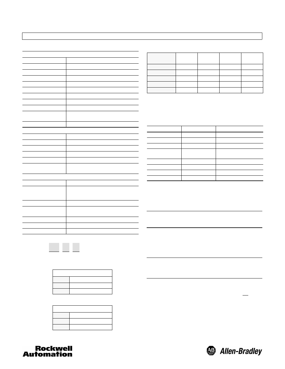
Selection
842A — 31
G B
a
b c
a
Code Type
Code
Description
31
36mm Pilot, 10mm Shaft
56
50mm Pilot, 6mm Shaft
b
Code Type
Code
Description
G
Gray Code
N
Natural Binary
c
A-B
Code
Pulses
Per Rev.
SSI Bits
MSB- LSB
No. of
Revs.
SSI Bits
MSB- LSB
A
8192
12--24
2048
1--11
B
4096
13--24
4096
1--12
C
2048
14--24
8192
1--13
D
4096
13--24
512
4--12
E
4096
13--24
256
5--12
Electrical Connections
The 842A comes with an M23 connector. The mating
connector, 845--12P, or pre-wired cable and connector
assembly 845--CA--G--* must be ordered separately. See
Encoder Accessories in the Sensors catalog.
Function
Pin Number
Description
DC Return
1
Ground
Data +
2
SSI
Clock +
3
SSI
DC + Input
8
10--32V DC
150mA no load
Reset
9
Data --
10
SSI
Clock --
11
SSI
CW/CCW
12
See below
Reset to zero is enabled when Pin 9 is momentarily connected to DC+ Input.
When pin 12 is connected to DC + (or left floating), the 842A will count UP when
the shaft is turned CW when looking at the shaft. When pin 12 is connected to DC
return, the 842A will count UP when the shaft is turned in the CCW direction when
looking at the shaft.
IMPORTANT: Wiring must be in accordance with the
National Electric Code and applicable local
codes and ordinances.
Mounting Instructions
1. Be sure to select the proper size flexible coupling clamp to
mate to the encoder shaft, e.g., 845--FC--*--*. See
Encoder Accessories in Sensor catalog.
IMPORTANT: Do not rigidly connect the encoder shaft to
the machine; this will cause premature
failure of the encoder or machine bearings.
Always use a flexible coupling.
2. Use the dimension drawings to determine the encoder
mounting hole locations.
3. Slide the flexible coupling onto the shaft, but do not tighten
the set screws.
4. Mount the encoder and tighten with three size M4
mounting screws (not supplied).
5. Center the flexible coupling and tighten the set screws.
6. Rotate the machine slowly and verify that the flexible
coupling is not deforming beyond specifications.
7. Align machine to its mechanical zero or home position.
Remove slotted cover located on the back of the encoder
and press the Reset button to make the encoder count
zero. Replace cover.