Dimensions—mm (inches) – Rockwell Automation 844D Optical Incremental Encoder User Manual
Page 3
3
844D
Blind-Shaft Tolerance
SIze
Bore
Mating Shaft
Length
1/2I
0.500/0.501
0.500/0.499
0.70/2.00
5/8I
0.625/0.626
0.625/0.624
0.70/2.00
3/4I
0.750/0.751
0.750/0.749
0.70/2.00
7/8I
0.875/0.876
0.875/0.874
0.70/2.00
1.0I
1.000/1.001
1.000/0.999
0.70/2.00
1 1/8I
1.125/1.126
1.125/1.124
0.70/2.00
30mm
30.000/30.025mm
30.000/29.975mm
18/50mm
844D
Through-Shaft Tolerance
Size
Bore
Mating Shaft
LengthĊmin.
1/2I
0.500/0.501
0.500/0.499
0.70
5/8I
0.625/0.626
0.625/0.624
0.70
3/4I
0.750/0.751
0.750/0.749
0.70
7/8I
0.875/0.876
0.875/0.874
0.70
1.0I
1.000/1.001
1.000/0.999
0.70
1 1/8I
1.125/1.126
1.125/1.124
0.70
30mm
29.980/29.959mm
30.000/29.975mm
18mm
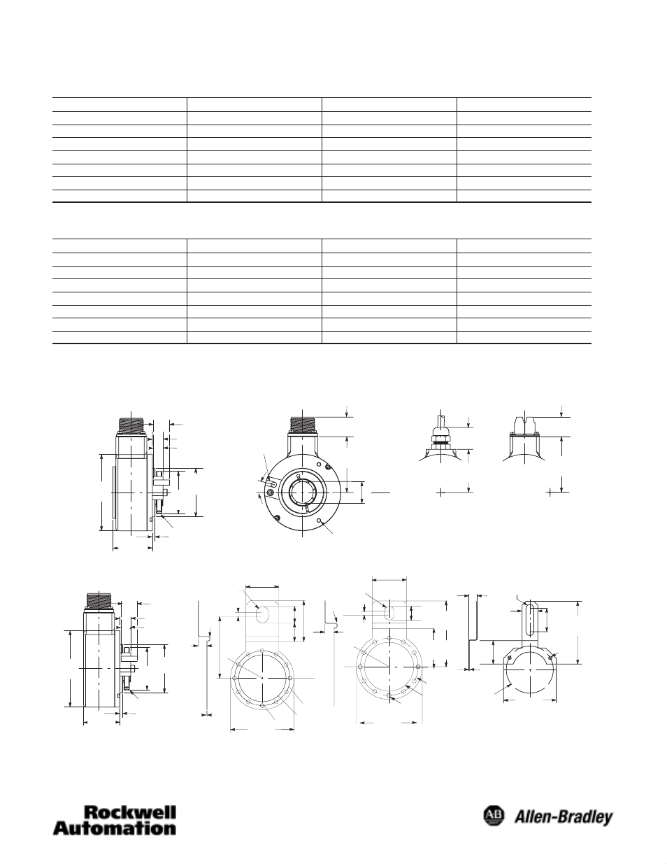
Dimensions—mm (inches)
∅57.15
(2.25)
∅50.0
(1.97)
∅57.15
(2.25)
∅89.66
(3.53)
∅89.66
(3.53)
∅50.0
(1.97)
#10-32UNC-28
X0.25 DP (3) Plcs
on a 3.000 B.C.
19.05 (0.75)
Blind-Shaft
Ê
Through-Shaft
Ê
Tether Option “C”
12.7 (0.50)
11.43 (0.45)
3.17 (0.125)
Clamp Ring
46.23
(1.82)
23.11
(0.91)
65.53
(2.58)
∅1.0008
1.0028 Bore
50.8
(2.00)
25.4
(1.00)
65.53
(2.58)
18.16
(0.71)
Connector
Option
Cable
Option
Terminal
Option
19.05 (0.75)
12.7 (0.50)
11.43 (0.45)
Clamp Ring
3.17 (0.125)
43.18
(1.70)
6.35/6.36
(0.25)
AntiĆRotation
Pin
15_
13.21
(0.52)
38.10
(1.50)
25.4
(1.0)
38.1
(1.5) 101.6
(4.0)
∅0.218
2 Plcs
∅76.2
(3.0)
85.3
(3.36)
Tether Option “B”
Tether Option “A”
12.78/12.73
(0.503/0.501)
30
_
107.5
(4.23)
51
(2.0)
22.4
(0.89)
16.94
(0.673)
7.14
(0.28)
12.7
(0.50)
87.3
(3.44)
87.1
(3.43)
5.59
(0.22)
76.2 (3.0)
65.0 (2.56)
38.1 (1.5)
12.7
(0.5)
7.14
(0.28)
12.7
(0.5)
5.59
(0.22)
38.1 (1.5)
76.2 (3.0)
65.0 (2.56)
5.59
(0.22)
87.3
(3.44)
87.5
(3.45)
18.2
(0.72)
51
(2.0)
30
_
Ê
Shown with optional anti-rotation pin.