Actuator consideration, Location and installation – Rockwell Automation 802B Small Precision Limit Switch User Manual
Page 2
Publication 75043–002–01(B)
February 2001
Printed in Japan
Visit our web site at:
http://www.ab.com/sensors
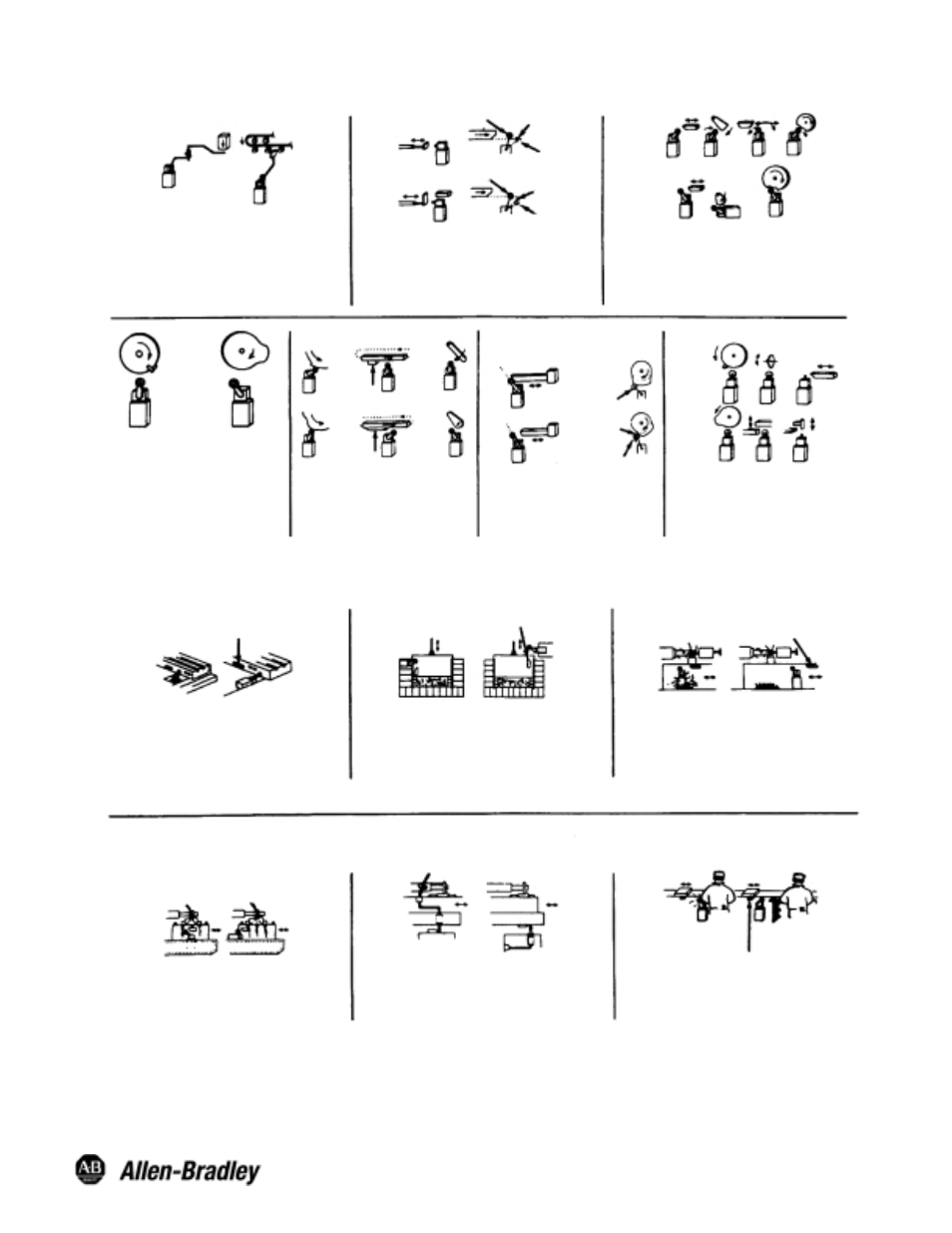
Actuator Consideration
Limit switches are designed for proper performance with
the actuators with which they are supplied.
Supplementary actuators should not be used unless the
limit switches are specifically designed for them.
Wrong
Wrong
Free Position
Interference
Wrong
Wrong
Right
Right
End of
Overtravel
Wrong
End of
Overtravel
Operated
Position
Free Position
Operating mechanism for limit switches should be so
designed that under any operating or emergency
conditions the limit switch is not operated beyond its
overtravel limit position. A limit switch should not be used
as a mechanical stop.
For limit switches with lever actuators, the actuating force
should be applied as nearly perpendicular to the lever as
practical and perpendicular to the shaft axis about which
the lever rotates.
NonĆOverriding
Right
NonĆOverriding
Wrong
Right
Where relatively fast motions are involved
cam arrangements should be such that
the actuator does not receive a severe
impact. Cams should be designed such
that the limit switch will be held operated
long enough to operate relays, valves, etc.
Cam or dog arrangements should be such
that the actuator is not suddenly released
to snap back freely.
A limit switch actuator must be allowed to
move far enough for positive operation of
the contacts.
For limit switches with pushrod actuators
the actuating force should be applied as
nearly as possible in line with the pushrod
axis.
Wrong
Overriding Cam
Right
Overriding Cam
Wrong
Right
Wrong
Right
Cam
Actuator
Free Position
Right
Operating
Position
Wrong
Right
Wrong
Cam
Operating
Position
Operated
Position
Location and Installation
Cam
Wrong
Right
Limit switches should be mounted rigidly and in
readily accessible locations with suitable
clearances to permit easy service and replacement
when necessary. Cover plates should face the
maintenance access point.
Limit switches should not be used in locations
where temperature or atmosphere conditions are
beyond those for which they have been specifically
designed.
Limit switches should be placed in locations where
machining chips do not accumulate under normal
operating condictions.
NonĆoverriding
Cam
Wrong
Right
NonĆoverriding
Cam
Wrong
Right
Wrong
Right
Limit switches should not be submerged in or
splashed with oils, coolants or other liquids.
Wrong
Right
The location of oiltight limit switches and the method of
connecting them should be such that condensation in the
conduit cannot enter the switch enclosure.
Wrong
Right
NonĆoverriding
Cam
Limit switches should be mounted in locations
which will prevent false operation by normal
movements of operator or machine components.