Dimensions, Frame e, Frame a...c wiring the control module fan – Rockwell Automation 25B PowerFlex 520-Series Control Module Fan Kit User Manual
Page 2: Frame d
PowerFlex 520-Series Control Module Fan Kit Installation
Publication 520-IN004B-EN-P - September 2013
Supersedes Publication 520-IN004A-EN-P - December 2012
Copyright © 2013 Rockwell Automation, Inc. All rights reserved.
Allen-Bradley, Rockwell Software, Rockwell Automation, PowerFlex, and TechConnect are trademarks of Rockwell Automation, Inc.
Trademarks not belonging to Rockwell Automation are property of their respective companies.
U.S. Allen-Bradley Drives Technical Support - Tel: (1) 262.512.8176, Fax: (1) 262.512.2222, E-mail: [email protected]
Online:
b
a
d
52.0 (2.05)
c
e
Dimensions
4
Frame E
All dimensions are in mm (in.)
Esc
Sel
b
32.0 (1.26)
e
d
c
a
Frame A...C
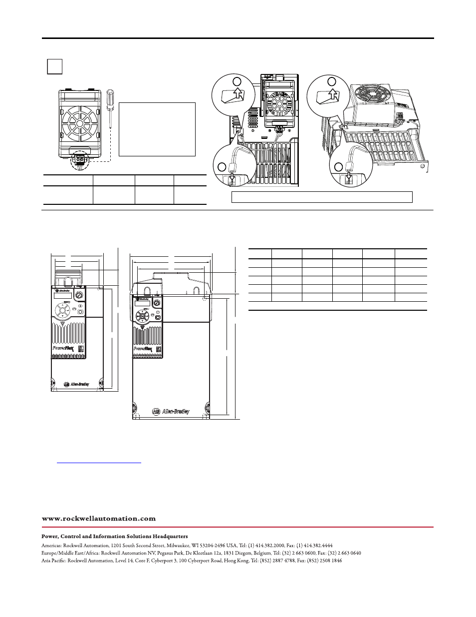
Wiring the Control Module Fan
Frame E
Frame A...D
Frame D
Note: Remove the label to access the built-in 24V supply on drive frames D and E.
Wire Size
Torque
Voltage
Amps
0.32 mm
2
(22 AWG)
0.29...0.39 Nm
(2.6...3.47 lb-in)
22.8...27.6V DC
0.10...0.15 A
Note: An external 24V DC power
source is required when using
the Control Module Fan Kit with
drive frames A, B, and C.
Frames D and E have a built-in
24V supply.
Frame
a
b
c
d
e
A
72.0 (2.83)
57.5 (2.26)
56.0 (2.20)
140.0 (5.51)
152.0 (5.98)
B
87.0 (3.43)
72.5 (2.85)
56.0 (2.20)
168.0 (6.61)
180.0 (7.09)
C
109.0 (4.29)
90.5 (3.56)
56.0 (2.20)
207.0 (8.15)
220.0 (8.66)
D
130.0 (5.12)
116.0 (4.57)
56.0 (2.20)
247.0 (9.72)
260.0 (10.24)
E
185.0 (7.28)
160.0 (6.30)
196.0 (7.72)
280.0 (11.02)
300.0 (11.81)
Note: Frames D and E cannot be mounted on a DIN-rail.
a
b
a
b