Rockwell Automation 599-xxxx DC Coil Controller User Manual
Installation
1
2
BULLETIN 599 DC COIL CONTROLLER KIT
INSTRUCTION SHEET
42052-124
OF
N/A
N/A
N/A
REVISION
AUTHORIZATION
DR.
CHKD.
APPD.
DATE
DATE
DATE
E - DOC
LOCATION: MILWAUKEE, WISCONSIN U.S.A.
B-vertical.ai
DWG.
SIZE
SHEET
B
1
2
3
4
5
6
7
8
A
B
C
D
E
G
H
REFERENCE
DIMENSIONS APPLY BEFORE
SURFACE TREATMENT
(DIMENSIONS IN INCHES)
TOLERANCES UNLESS
OTHERWISE SPECIFIED
.XX:
.XXX:
ANGLES:
42052
G. Ushakow
8-17-05
8-17-05
8-17-05
M.A. Jutz
D. Josef
ATTENTION: To prevent electrical shock, disconnect from power source before installing or servicing. Install
in suitable enclosure. Keep free from contaminants.
* Logic device should be capable of switching the larger of initial inrush current or maximum DC
inrush current.
DC Coil Controller Kit
(Cat 599-B24DC, -C24DC, -D24DC, -B250DC, -C250DC, -D250DC)
Conversion Kit Selector Chart
Installation
1
1014084
2
1015746
THIS DRAWING IS THE PROPERTY OF
ROCKWELL AUTOMATION, INC.
OR ITS SUBSIDIARIES AND MAY NOT BE COPIED,
USED OR DISCLOSED FOR ANY PURPOSE
EXCEPT AS AUTHORIZED IN WRITING BY
ROCKWELL AUTOMATION, INC.
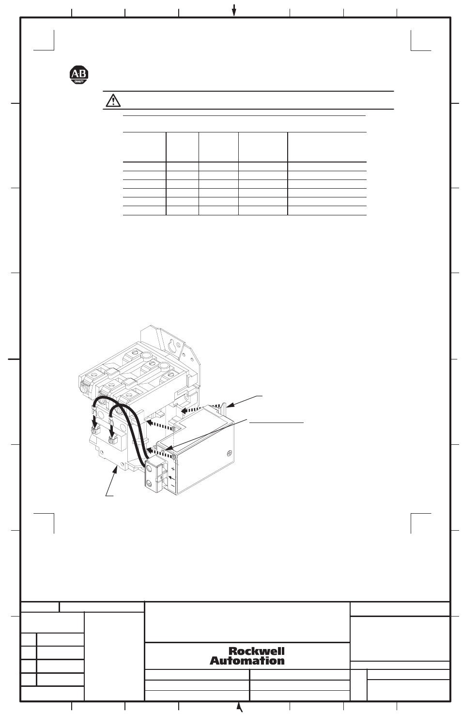
1) Remove Coil Cover and all control wires.
2) Pull out coil and yoke assembly.
3) Install "Special" Coil from Bulletin 599 Kit.
4) Re-install coil cover and tighten screws to 10 - 16 lb-in.
5) Align Coil Controller so that (2) tabs insert into the underside of coil cover.
6) Push side of coil controller until clips snap into place.
7) Insert the (2) wires into Special Coil terminals and tighten to 8 -10 Lb-In.
8) Connect control power from adequate DC power source (e.g. Bulletin 1606) to Coil Controller.
LED Status Indication
Solid Green - Sufficient voltage for contacts to close.
Solid Yellow - Voltage is too low to attempt contact closing.
Flashing Yellow (once every second) - Controller has an
over-temperature condition and is not operative during this
condition.
No Color (LED Off) - Polarity is reversed - reverse wires.
Clips
Coil Cover
NEMA
Size
0 - 1
2
3
0 - 1
2
3
24V
24V
24V
125 ... 250V
125 ... 250V
125 ... 250V
6 A
6 A
6 A
3 ... 6 A
3 ... 6 A
3 ... 6 A
5.6 A
8.1 A
16.4 A
1.8 ... 0.9 A
2.4 ... 1.2 A
3.7 ... 1.9 A
599-B24DC
599-C24DC
599-D24DC
599-B250DC
599-C250DC
599-D250DC
Catalog
Number
Maximum DC Inrush
Switching Requirement
for Logic Control Device*
[< = 100mS / contactor closure]
Initial
Inrush
Current
< 11 mS
Voltage
DC
VOLTAGE
INPUT