Obsolete – Rockwell Automation 845S Incremental Encoder User Manual
Page 2
Obsolete
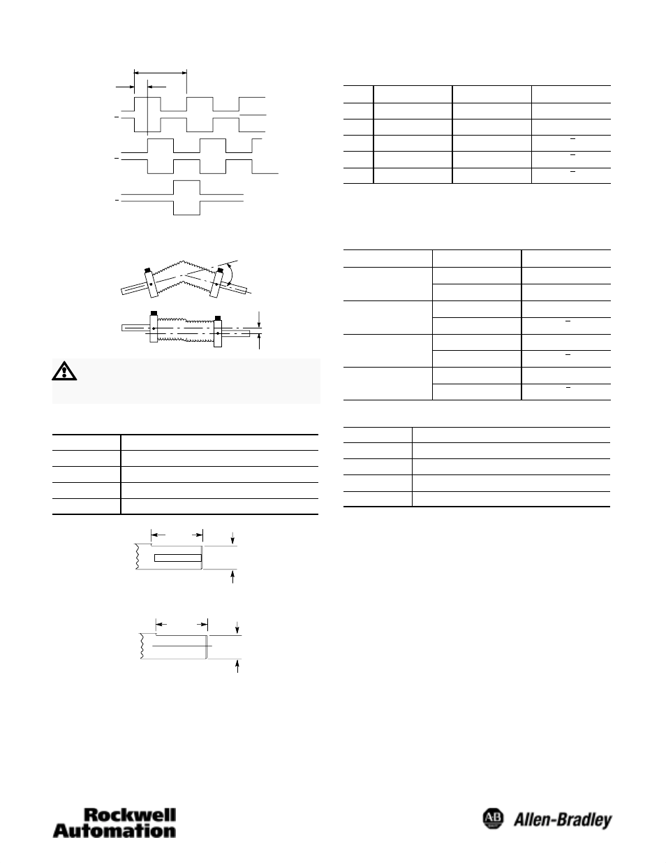
Differential Line Driver Output Waveform:
90 +/- 22
°
Channel A
Channel A
Channel B
Channel B
(Index)Channel Z
Channel Z
1 Cycle
Logic 1
Logic 0
(CCW Rotation Shown)
Flexible Shaft Couplings
Angle
Parallel
OffĆSet
ATTENTION: Rigidly coupling the encoder shaft
to the machine shaft will cause a failure in either
the bearings of the encoder or the bearings of the
machine shaft.
Shaft Diameter Options
Code
Shaft Diameter
A or K
6mm +0.00mm, -0.013mm
B or L
10mm +0.00mm, -0.013mm
C or M
6.35 (0.2499) +0.0000, -0.0005
Z or N
9.52 (0.3749) +0.0000, -0.0005
18.3
(0.72)
3/8
I
Dia. Double Flat
Shaft
9.1
(0.36)
19.05
(0.75)
Shaft with Flat Option
A
10-Pin Connector ACS02E18–1P (023) or Equivalent
Differential LineĆDriver Outputs
Pin
Function
Pin
Function
A
Channel A Output
F
DC Return
B
Channel B Output
G
Shield Ë
C
Channel Z Output
H
Channel A Output
DÊ
DC+ Input
I
Channel B Output
EÊ
Ċ
J
Channel Z Output
Ê
Pins D and E internally connected
Ë
Pins G not connected to case ground.
Cable
Differential Line Driver Outputs
Wire Pair
Wire Color
Function
Red/Black
Red
DC+ Input
Red/Black
Black
DC Return
White/Black
White
Channel A Output
White/Black
Black
Channel A Output
Blue/Black
Blue
Channel B Output
Blue/Black
Black
Channel B Output
Green/Black
Green
Channel Z Output
Green/Black
Black
Channel Z Output
Flat Dimensions
Code
Dimension A"
K
5.3mm (0.21in)
L
9.1mm (0.36in)
M
5.5mm (0.22in)
N
8.6mm (0.34in)