Rockwell Automation 802T 802T 4-Circuit Direct Opening Action Limit Switch User Manual
Page 2
S
Grounding of switch should be achieved per National
Electric Code (NFPA 70) requirements. Grounding terminal
is located in the terminal block housing.
S
Arrange control wiring according to terminal markings.
S
Tighten terminal screws according to specifications.
S
Only use insulated connectors.
Important: Pay close attention to the terminal
numbering on the terminal block when
wiring this switch. Terminals 1 and 2 or 5
and 6 are normally open contacts.
Terminals 3 and 4 or 7 and 8 are normally
closed contacts.
Actuator Head Positioning
The actuator head may be placed in any of four positions on
the switch body. Loosen the four captive screws. Place the
head in the desired position and securely retighten the four
screws (see figure below).
Lever Positioning
The lever on rotary actuated devices is adjustable to any
position through 360
_
around the shaft. Loosen the nut, move
the lever to the desired position and securely retighten the nut
(see figure below).
Lock Pin
Nut
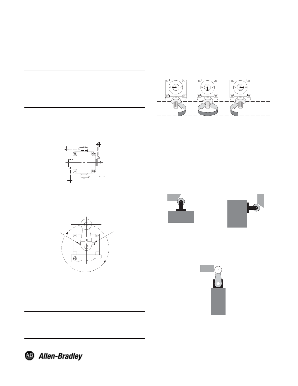
Changing Direction of Actuation
The switch action of lever operated limit switches may be
adjusted to operate with either a clockwise, a
counterclockwise or both directions movement of the shaft.
To change the actuation direction, follow the steps below:
Important: This procedure must be performed in a
clean environment to avoid the
introduction of foreign material into the
operating mechanism.
Step 1: Loosen the four head mounting screws and remove
the operating head from the switch body.
Step 2: Locate the plunger on the underside of the operating
head.
Step 3: Pull the plunger outward and rotate it in steps of 90
_
to provide the operating mode desired. The
respective settings are shown in the figure below.
CCW Only
CW Only
CW & CCW
Plunger
Setting
Actuation
Required
Step 4: Make sure the plunger is pushed back inward and
the “O” ring is properly seated before the operating
head is reattached to the switch body.
Step 5: Securely retighten the operating head mounting
screws.
Step 6: Check for the desired actuation mode.
Methods of Actuation Examples
802T–KPD
Side Push Roller
30
_
Non-Overtravel Dog
802T–DPD
Top Push Roller
30
_
Non-Overtravel Dog
Vmax = 30ft/min @ actuator
F max = 150 cycles/min
802T–APD
802T–W1A 1.5
I
Long
90
_
Non-Overtravel Dog
Vmax = 30ft/min @ actuator
F max = 150 cycles/min
Publication 75023–092–01(A)
September 2002
Printed in USA