Status/diagnostic operating led indicators, 4 440g-lz guard locking switch – Rockwell Automation 440G-LZ Guard Locking Safety Switch Installation Instructions User Manual
Page 4
Publication 440G-IN011-EN-P — October 2013
Copyright © 2013 Rockwell Automation, Inc. All rights reserved. Printed in the USA.
Allen-Bradley and Rockwell Automation are trademarks of Rockwell Automation, Inc. Trademarks not belonging to Rockwell Automation are property of their respective companies.
4 440G-LZ Guard Locking Switch
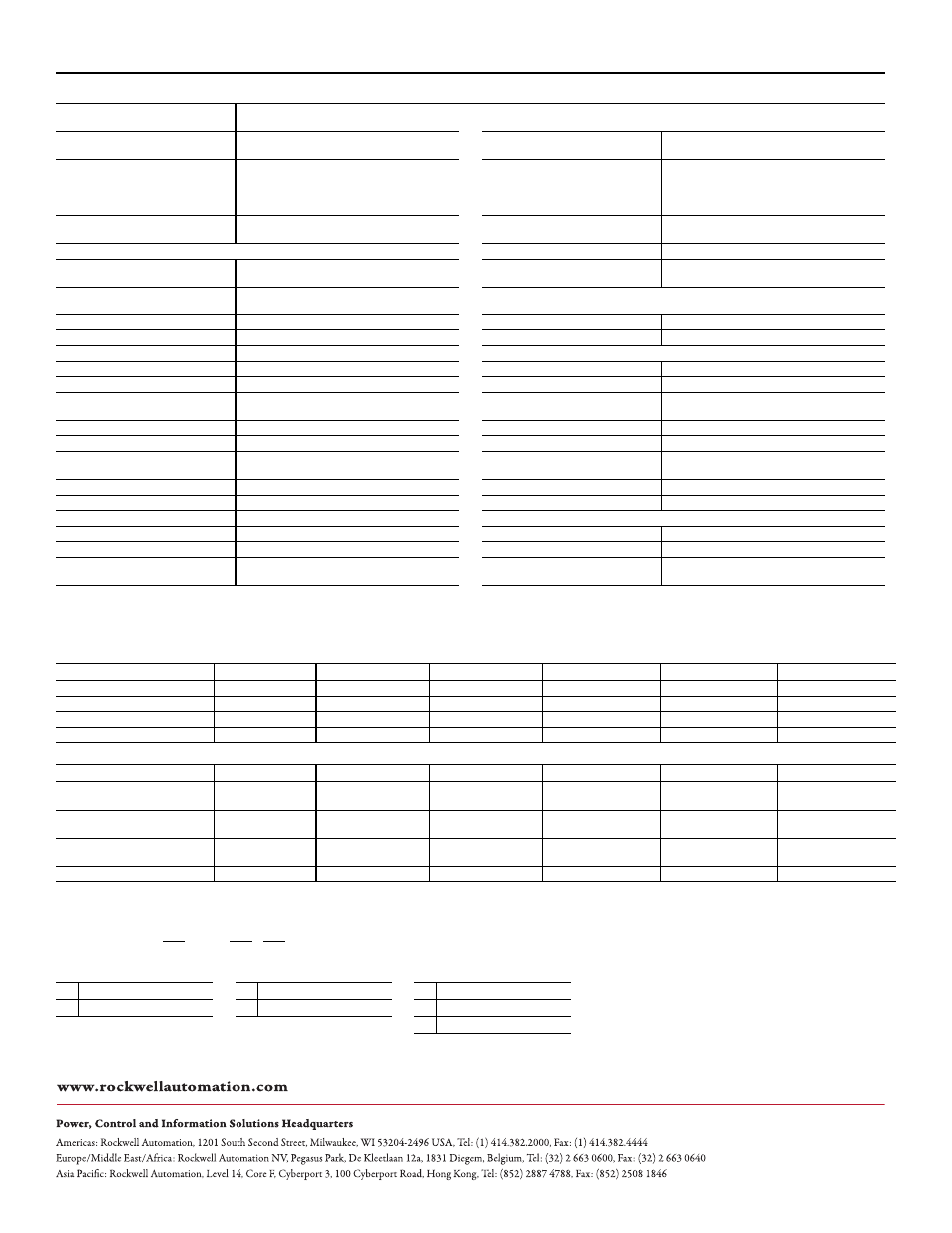
Status/Diagnostic Operating LED Indicators
The switch has two pairs of LEDs, status LEDs are green and diagnostic LEDs are red.
Catalog Numbers for Complete Switches
Specifications
Standards
IEC 60947-5-3, IEC 60947-5-1, IEC 61508, EN ISO 13849-1, IEC
62061, ISO 14119, UL 508
Operating Characteristics (continued)
Safety Classification: Guard door sensing and lock
monitoring
PLe Category 4 per ISO 13849-1, SIL 3 per IEC 61508 and IEC 62061
Impulse withstand voltage Uimp (IEC 60947-1)
1 kV
Functional Safety Data: Guard door sensing and lock
monitoring
PFHd: 9.1 x 10
-10
; Dual channel interlock can be suitable for use in
application up to PLe (according to ISO 13849-1) and for use up to
SIL3 systems (according to IEC 62061 and IEC 61508) depending
on application characteristics. Mission time/PTI: 20 years
Pollution degree (IEC 60947-1)
3
Certifications
CE Marked for all applicable EU directives, cULus (UL 508), TÜV, C-
tick
Manual (auxiliary) release
Built in
Operating Characteristics
Protection class (IEC 61140)
Class II
Torque for M5 mounting of switch and actuator
mounting bracket
2 Nm max.
Mechanical life
500,000 cycles
Locking bolt insertion for assured locking & holding
force
Min. of 5 mm (0.19 in.), max. of 10 mm (0.39 in.)
Outputs (Guard door closed and locked)
Locking bolt alignment tolerance X, Y, Z
Max. of ±2.5 mm (0.09 in.)
Safety Outputs
2 x PNP, 0.2 A max / ON (+24V DC)
Holding Force Fmax (EN/ISO 14119)
1,690 N
Auxiliary Outputs
1 x PNP, 0.2 A max / OFF (0V DC)
Holding Force Fzh (EN/ISO 14119)
1,300 N
Environmental
Maximum output current (each outputs)
200 mA
Operating temperature [C (F)]
0…+55° (+14…+131°)
Quiescent power consumption, locked or unlocked
2.5 W
Storage temperature [C (F)]
-25…+75° (-13…+167°)
Peak current and duration, at turn on or after lock/
unlock operation
400 mA / 100 ms
Operating humidity
5…95% relative
Operating voltage Ue
24V DC +10% / -15% Class 2 SELV
Enclosure ingress rating
NEMA 3, 4X, 12, 13, IP66, IP67, IP69k
Maximum frequency of operating cycles
0.2 Hz
Shock and vibration
IEC 60068-2-27 30 g, 11 ms/IEC 60068-2-6 10…55 Hz
Dwell time between subsequent locking/unlocking 2.5 s
Hygienic
ISO 14159:2004 and EN 1672-2005, (for that part of the machine
defined as “food splash area”)
Response time (Off)
100 ms first switch, 50 ms additional for each switch
Washdown
Sodium Hydroxide based washdown fluids
Risk Time (according to IEC 60947-5-3)
100 ms
Radio frequency / EMC
IEC 60947-5-3, FCC-1(Parts 18&15), R&TTE
Start up time (availability)
5 s
General
Maximum length of a chain of switches
10 km (Dependent on cable/connection/required response time)
Materials
ABS, locking bolt and mounting bracket 304 stainless steel
Utilization category (IEC 60947-5-2)
DC-13 24V 200 mA
Weight switch/actuator
Switch 400 g, actuator 150 g, actuator mounting bracket 60 g
Insulation voltage Ui (IEC 60947-1)
75V
Protection Type
Short-circuit, current limitation, overload, reverse polarity,
overvoltage (up to 60V max.), thermal shutdown/restart
Power to Lock Versions
Door/Guard Status
Lock Command
OSSD Input
Lock Status
LED Status
OSSD Status
Power on and lock command off
Open or closed
Off
Off or on
Unlocked
Blinks 6 x green then solid red
Off
Lock command on and door open
Open
On
Off or on
Unlocked
Fast flash green
Off
Lock command on and door closed
Closed
On
Off
Locked
Slow flash green
Off
Lock command on and door closed
Closed
On
On
Locked
Solid green
On
Power to Release Versions
Door/Guard Status
Unlock Command
OSSD Input
Lock Status
LED Status
OSSD Status
Power on with door open
Open
Off
Off or on
Unlocked
Blinks 6 x green then 1 x blink red
followed by fast flash green
Off
Power on with door closed
Closed
Off
Off
Locked
Blinks 6 x green then 1 x blink red
followed by slow flash green
Off
Power on with door closed and OSSD input
active
Closed
Off
On
Locked
Blinks 6 x green then 1 x blink red
followed by solid green
On
Unlock command on and door closed or open Open or closed
On
Off or on
Unlocked
Solid red
Off
440G-LZS21
P
a
b
c
a
b
c
S
Standard Coding
R
Power-to-Release
A
3 m Cable
U
Unique Coding
L
Power-to-Lock
B
10 Cable
H
M12 8-pin