Rockwell Automation 284E- ArmorStart Control Module Replacement User Manual
Armorstart control module replacement
1
1
ARMORSTART CONTROL MODULE REPLACEMENT
INSTRUCTION SHEET
1
1024185
41053-389
OF
N/A
N/A
N/A
REVISION
AUTHORIZATION
DR.
CHKD.
APPD.
DATE
DATE
DATE
E - DOC
LOCATION: MILWAUKEE, WISCONSIN U.S.A.
B-vertical.ai
DWG.
SIZE
SHEET
B
1
2
3
4
5
6
7
8
A
B
C
D
E
F
G
H
REFERENCE
DIMENSIONS APPLY BEFORE
SURFACE TREATMENT
(DIMENSIONS IN INCHES)
TOLERANCES UNLESS
OTHERWISE SPECIFIED
.XX:
.XXX:
ANGLES:
41053
THIS DRAWING IS THE PROPERTY OF
ROCKWELL AUTOMATION, INC.
OR ITS SUBSIDIARIES AND MAY NOT BE COPIED,
USED OR DISCLOSED FOR ANY PURPOSE
EXCEPT AS AUTHORIZED IN WRITING BY
ROCKWELL AUTOMATION, INC.
G. Ushakow
7-28-06
7-28-06
7-28-06
M. Jutz
B. Griffin
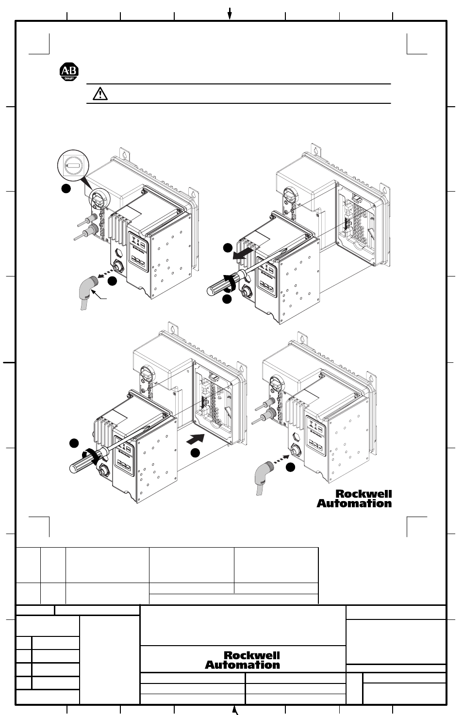
ArmorStart Control Module Replacement
Installation of Control Module
Removal of Starter Module
Motor Cable
ATTENTION: To prevent electrical shock, disconnect from power source before installing or servicing.
1) Disconnect from power source.
2) Remove motor cable.
3) Loosen the four mounting screws.
4) Unplug the Control Module from the base by pulling forward.
1) Install Control Module.
2) Tighten the four mounting
screws.
3) Install motor cable.
Accessory 193-EIMD Shown
2
1
2
3
1
41053-389-01 (1)
Printed in U.S.A.
PART
NO.
MATERIAL
CHG.
CHAR.
FLAT
FOLD
SIZE
-01
1
ONE SIDE PRINTED
8-1/2" W x 11" H
BODY STOCK WHITE
BODY INK BLACK
4-1/4" W x 5-1/2" H
30 lb-in
1
2
3
3
4
1
2