Rockwell Automation 440P-WM3 Metal Rod Lever Installation/Operating Instructions User Manual
Page 2
Copyright © 2012 Rockwell Automation, Inc. All Rights Reserved.
10000101187 Ver 01
June 2012
Power, Control and Information Solutions Headquarters
Americas: Rockwell Automation, 1201 South Second Street, Milwaukee, WI 53204-2496 USA, Tel: (1) 414.382.2000, Fax: (1) 414.382.4444
Europe/Middle East/Africa: Rockwell Automation NV, Pegasus Park, De Kleetlaan 12a, 1831 Diegem, Belgium, Tel: (32) 2 663 0600, Fax: (32) 2 663 0640
Asia Pacific: Rockwell Automation, Level 14, Core F, Cyberport 3, 100 Cyberport Road, Hong Kong, Tel: (852) 2887 4788, Fax: (852) 2508 1846
www.rockwel lautomation.com
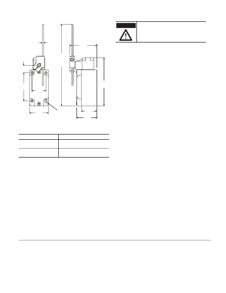
Mounting Dimensions [mm (in.)]
Torque Specifications
Maintenance
These devices require little maintenance, but routine visual
inspection is recommended to keep foreign debris from
collecting on the exterior actuators and rollers.
Removing the operator head is not recommended as loose
internal components may be lost or improperly re-installed.
Actuation Guidelines
The method of actuation and over travel has significant
influence on the service life of the limit switch. To maximize
the service life, it is recommended to provide an actuator with
a 30° pressure angle and a surface hardness of RC-45 max.
Location
Torque
Rod lever 3 mm Allen
head screw
1.5…2.1 N•m (13.28…18.59 in•lb)
Collar shaft 3 mm Allen
head screw
2.7…3.7 N•m (23.9…32.75 in•lb)
60
(2.36)
16
(0.62)
3
(0.12)
dia.
43
(1.69)
40
(1.57)
30
(1.18)
57
(2.24)
240
(9.44)
103
(4.05)
33
(1.29)
Max.
Extension
4 x M5
Mounting holes
Under no circumstances must the switch be
actuated beyond the mechanical travel
specified. Serious damage to the device and
property could result.
ATTENTION