Installation, Timing diagram, Dimensions-[mm (in.) – Rockwell Automation 871P DC Inductive Proximity Can Motion Sensor User Manual
Page 2
Copyright © 2012 Rockwell Automation, Inc. All Rights Reserved.
75021-024-01 Ver 03
Power, Control and Information Solutions Headquarters
Americas: Rockwell Automation, 1201 South Second Street, Milwaukee, WI 53204-2496 USA, Tel: (1) 414.382.2000, Fax: (1) 414.382.4444
Europe/Middle East/Africa: Rockwell Automation NV, Pegasus Park, De Kleetlaan 12a, 1831 Diegem, Belgium, Tel: (32) 2 663 0600, Fax: (32) 2 663 0640
Asia Pacific: Rockwell Automation, Level 14, Core F, Cyberport 3, 100 Cyberport Road, Hong Kong, Tel: (852) 2887 4788, Fax: (852) 2508 1846
www.rockwel lautomation.com
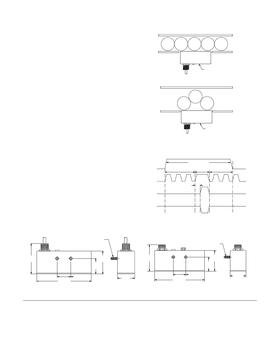
Installation
Select the location for sensor mounting. Ensure that the target to
sensor clearance is approximately 6.4 mm (0.25 in.), the sensor is
at least 51mm (2 in.) away from other proximity sensors, and there
are no metal objects adjacent to the sensor's face or sides that
may distort the sensing field. Mount the sensor using 871A-BR58
sensor bracket mounting assembly or other suitable bracketing.
Route the sensor's 4-conductor cable to a junction box. Connect
the cabling to the load device according to the appropriate wiring
diagram. Note that the maximum load current for either NPN or
PNP output is 300mA. The PNP (voltage source) output level
tracks the DC input voltage level.
Apply power to the sensor. Turn the Motion Adjust potentiometer
to its full counterclockwise position.
Position containers in front of the sensor as shown at right,
depending on the conveyor system to be used. Adjust the
position of the sensor forward until the output LED is on and
brightly lit.
Start the conveyor and run at normal line speed. Adjust the
Motion Adjust potentiometer clockwise so that the sensor is
detecting the peaks of the container and not the valleys. The
motion LED should flash dimly for each passing container.
If the LED fails to blink for each container, adjust the Motion
Adjust potentiometer clockwise or position the sensor closer to
the containers. If the LED remains on, turn the Motion Adjust
potentiometer counterclockwise or position the sensor farther
from the containers.
Stop the conveyor with containers in front of the sensor. The LED
should turn on brightly after 0.5 seconds. If the output LED fails to
turn on, adjust the position of the sensor inward until the LED
turns on.
Timing Diagram
Outside Rail
Motion Adjust
Motion Adjust
Presence
Circuit
Outputs
ON
Cans
Stopped
0.5 s
Delay
Cans in Motion
Metal Presence
Output
Sink
Output
Source
Motion
Circuit
Cans in Motion
44.45
(1.75)
140 (5.50)
39.62
(1.56)
58.67
(2.31)
1/4--20 x 0.63
2 Places
58.67
(2.31)
35.05 (1.38)
44.45
(1.75)
140 (5.50)
39.62
(1.56)
1/4-20 x 0.63
2 Places
76.45
(3.01)
70.6
(2.78)
871P-DD29NB140-A2
871P-DD29NB140-N4 and 871P-DD29NB140D4
35.05 (1.38)
Dimensions-[mm (in.)]