Figure 2 – Rockwell Automation SK-L1-CAP2-D1250 Filter Capacitor Kit SK-L1-CAP2-D1250 for PowerFlex 700L Fr. 3B 480V AC Drives User Manual
Page 6
6
Rockwell Automation Publication 20L-IN016A-EN-P - February 2012
Filter Capacitor Replacement Kit SK-L1-CAP2-D1250 for PowerFlex 700L Frame 3B 480V AC Drives
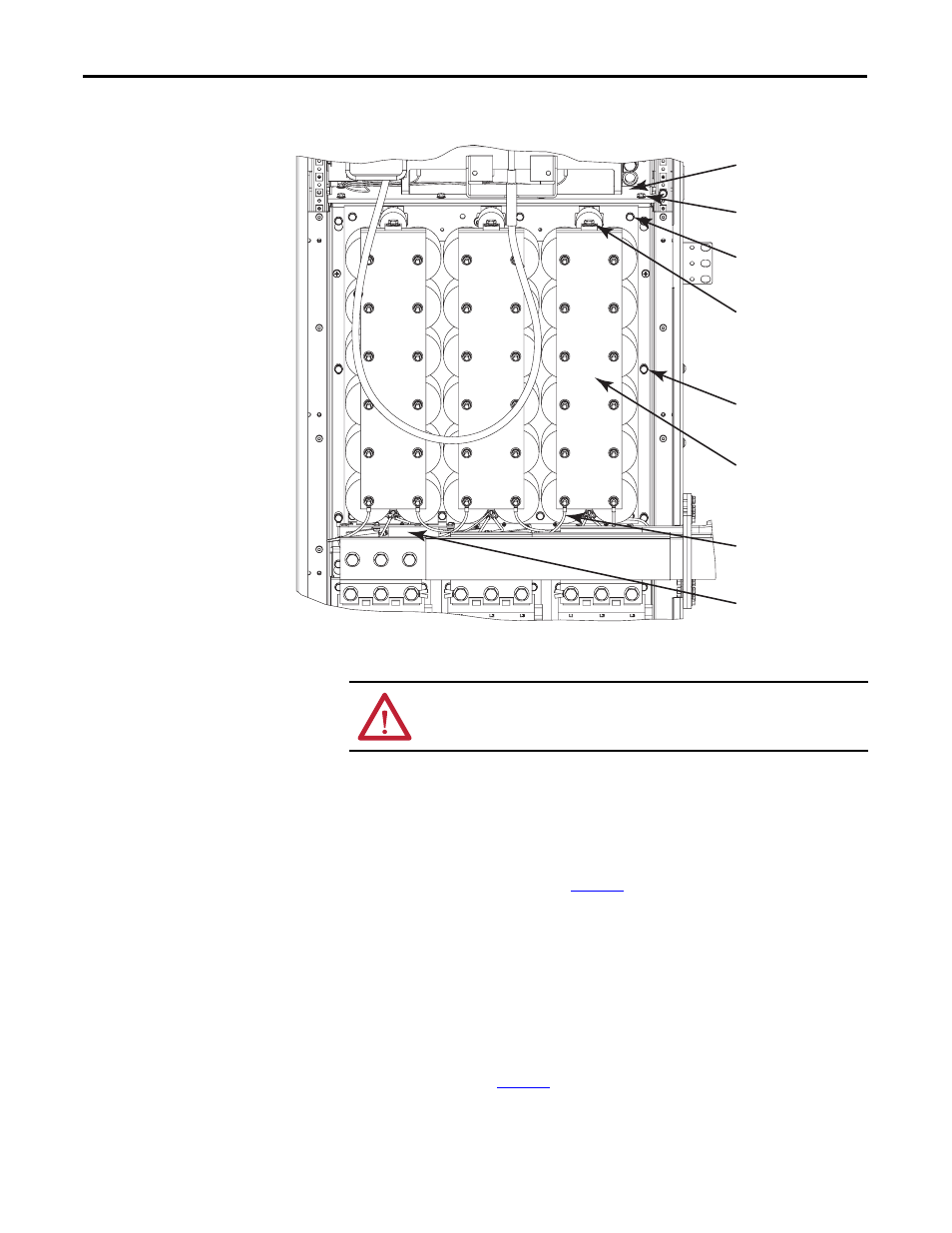
Figure 2 - Existing Filter Capacitor Assembly in Drive
Step 5: Remove the
Existing Filter
Capacitor Assembly
a. After power has been removed from the drive, the filter capacitor bank
should discharge via the bleeder resistor discharge network. Wait five
(5) minutes to fully discharge.
b. Carefully check for zero (0) volts between each of the three (3)
Capacitor Bus Bars (input power) and the Neutral Bus Plate at the
stake-on connectors (see
) using a confidence-tested DC
voltmeter.
c. Gain access to the left side of the enclosure. Remove and retain the
hardware that secures the left side panel to the enclosure, and remove
the panel and set it aside.
d. Cover any components under the capacitor bank to protect them from
any dropped hardware.
e. Place a piece of rigid cardboard or something similar on top of the three
(3) Bus Bars connected to the contactors to prevent any damage to the
Bus Bars (see
) or their protective coating.
1 μF Capacitor
Power Wires (3x)
(not shown)
Mounting Hardware (4x)
Harness for Bleeder
Resisitor network
Fiberglass Insulator Panel
Capacitor Bank
Mounting Hardware (6x)
Panel Mounting
Hardware (6x)
Capacitor Bus Bars (3x)
Input Power
ATTENTION: Upon removing the assembly and hardware, sharp edges may be
encountered. Use work gloves to protect your hands.