Step 6: install the emi shield and control board – Rockwell Automation 20P PowerFlex DC Drive - Frame C Field Snubber Circuit Board User Manual
Page 7
PowerFlex® DC Drive - Frame C Field Snubber Circuit Board
7
Step 4: Remove the
Existing Field Snubber
Circuit Board
Important: Mark all connections and wires before removal to avoid
incorrect wiring during reassembly.
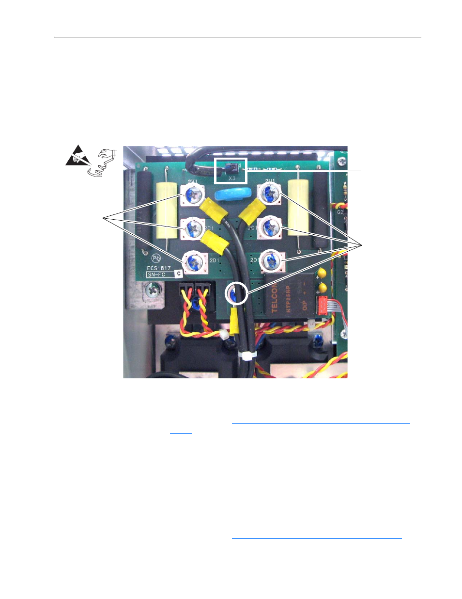
1. Remove the cable from connector X3 on the Field Snubber board.
2. Remove the seven screws, washers and wire leads (connections 2V1,
2U1 and 2C1 and one unmarked) from the board and remove the board
from the drive.
Step 5: Install the New
Field Snubber Circuit Board
Install the new Field Snubber circuit board in reverse order of removal and
detailed in Step 4:
Remove the Existing Field Snubber Circuit Board on
•
Tightening torque for the screws connecting the Field Snubber board to
the Field SCR and Dual Diode Modules is 2.5 - 4.0 Nm (22-35 lb.-in.).
•
Inspect the existing X3 and XFCD cables for burn marks, cracks or loose
connectors. If necessary, replace the cables on the Field board with the
new cables provided.
Step 6: Install the EMI
Shield and Control Board
Install the EMI Shield and Control board in reverse order of removal as
detailed in Step 3:
Move the EMI Shield and Control Board on page 5
.
=
Remove screws
and washers
Remove screws
and washers
Remove cable