Rockwell Automation 45AST Area Array User Manual
Page 2
2
Mounting the Sensor
To avoid intermittent operation, do not
mount the sensors to surfaces that may
shift or be exposed to excessive vibration.
ATTENTION
Securely mount the sensor on a firm, stable surface or
support. Once securely mounted, the sensor may be wired as
indicated in the wiring diagrams.
Maintenance
When cleaning the face of the sensor, do
not use aggressive or abrasive materials
which could reduce the operating range
and accuracy.
ATTENTION
Use a dry, soft cloth for cleaning the lens area.
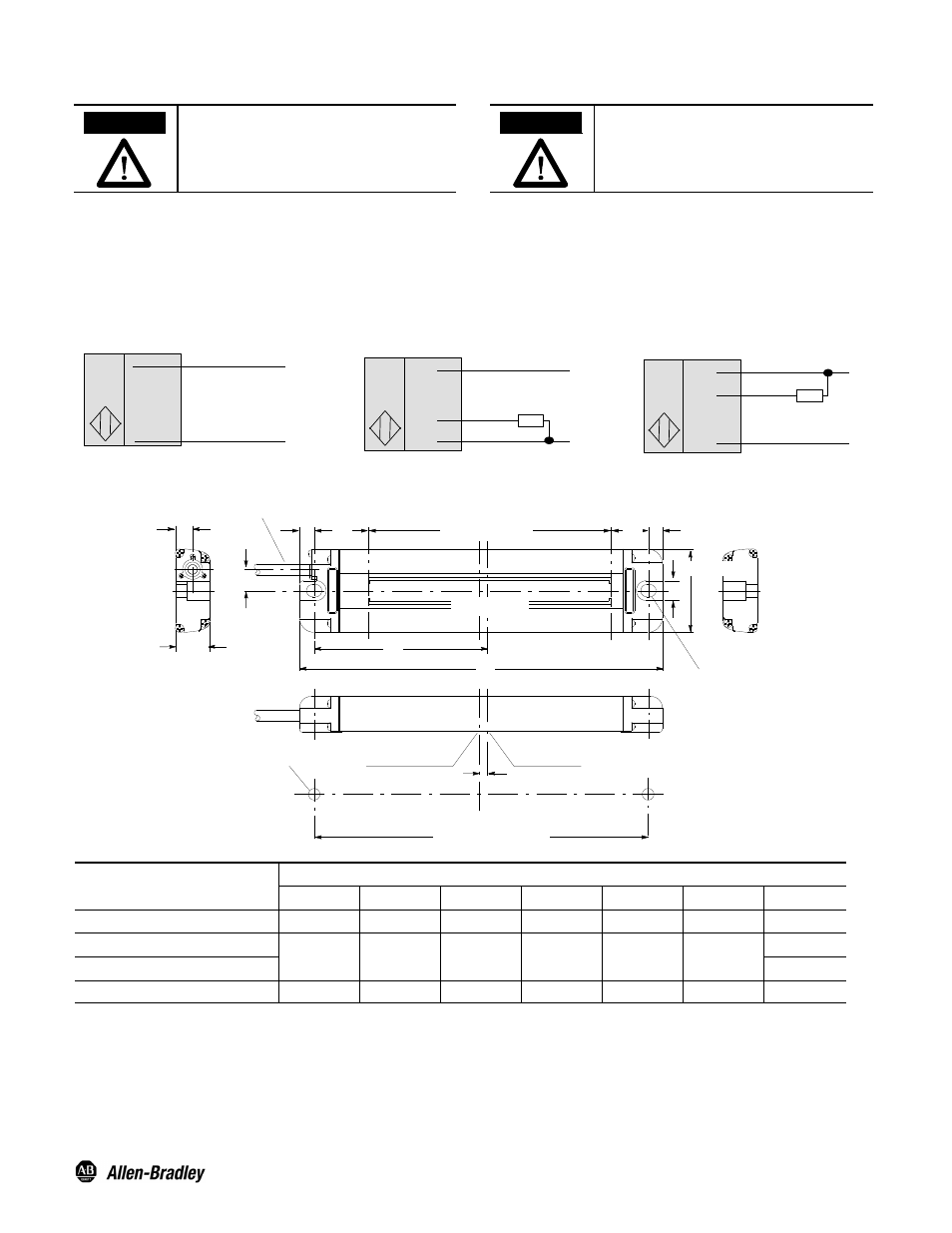
Wiring Diagrams
Quick disconnect connection is shown in the following diagrams. Pin numbers correspond to male connectors on the sensor.
+
--
Brown (1)
White (2)
Blue (3)
Load
Blue (3)
Brown (1)
+
--
Cable
NPN Output
PNP Output
+
--
Brown (1)
Black (4)
Blue (3)
Load
+
--
+
--
Cable
Cable
Emitter
Approximate Dimensions [mm in.]
9.0
(0.35)
Cable Dia. 4 (0.16)
PVC: 3 m (9.8 ft)
7.2
(0.28)
14.5
(0.57)
8.2
(0.32)
6.5
(0.25)
B (Detecting Width)
C
B
6.5
(0.25)
34 (1.33)
E
A
Detecting Width
Dia. 116.8 (4.6) x 2
Center of Installation
Hole Pitch
Center of Axis
F
G (Installation Hole Pitch)
2--M4
Model
[mm (in.)]
A
B
C
D
E
F
G
45AST--1JB1--4
100 (3.93)
50 (1.96)
22.5 (0.88)
14.5 (0.57)
47.5 (1.87)
4 (0.15)
87 (3.42)
45AST--1JB2--4
150 (5.9)
100 (3.93)
22 (0.86)
15 (0.59)
72 (2.83)
3.5 (0.13)
137 (5.39)
45AST--1JB3--4
137 (5.39)
45AST--1JB4--4
200 (7.87)
150 (5.9)
22 (0.86)
15 (0.59)
97 (3.81)
3.5 (0.13)
187 (7.36)
N = NPN and P = PNP.
Publication 10000106491 Ver 01
January 2012
Printed in USA
PHOTOSWITCHR is a registered trademark of Rockwell
Automation.