Step 5: remove the capacitor circuit board, Remove the capacitor circuit board – Rockwell Automation 23P PowerFlex DC Stand-Alone Regulator (SAR) Capacitor Circuit Board User Manual
Page 6
6
Rockwell Automation Publication 23P-IN005A-EN-P - June 2011
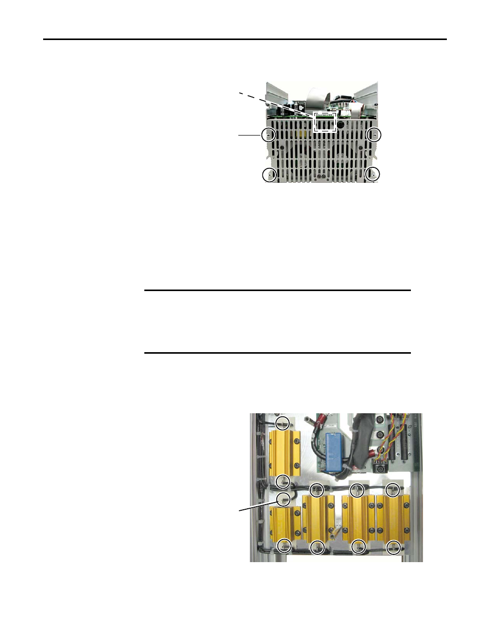
10. Remove the cooling vent mounting screws (4) on top of the stand-alone regulator,
and save for reassembly.
11. Disconnect the fan plug from the XV connector on the switching power supply
circuit board.
12. Remove the cooling vent and fan assembly.
13. Carefully slide the power interface circuit board and the switching power supply
circuit board assembly out of the chassis.
Step 5: Remove the
Capacitor Circuit
Board
1. Use a soldering iron to heat the solder on the in-rush limiting resistor and discharge
resistor wiring terminals until you can remove the wires from the terminals.
2. Remove the solder from the in-rush limiting resistor and discharge resistor terminals
so the new wires can be properly inserted into the terminals.
Cooling Vent Mounting
Screws (4)
Tightening torque:
1.0 N•m (8.9 lb•in)
Fan plug XV connector
(behind cooling vent)
IMPORTANT
The capacitor circuit board comes with the wiring harness for the in-rush
limiting resistor, discharge resistors, and plug to the power interface
circuit board already soldered to the capacitor circuit board. You need to
remove the solder from the in-rush limiting resistor and discharge
resistors wiring terminals so you can re-solder the new wiring harness
leads to the respective resistor wiring terminals.
Note: Depending on
sizing, the SAR may have
three, or four, discharge
resistors.
Remove the solder from
in-rush limiting resistor
and discharge resistor
wire terminals (8 or 10
terminals, depending on
sizing).