Dimensions [mm (in.)] wiring diagrams, Mounting [mm (in.), Teach interface – Rockwell Automation 45LUM-D7JPT1-D5 Luminescence Sensor User Manual
Page 2: How to teach the sensor
Rockwell Automation 45LUM-IN001A-EN-P — May 2014
2 45LUM Luminescence Sensor
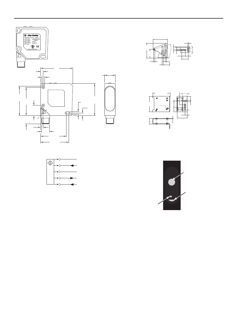
Dimensions [mm (in.)]
Wiring Diagrams
50
(1.97)
50
(1.97)
4
(0.16)
4.3
(0.17)
4.3
(0.17)
4
(0.16)
Teach instructions
1. Push set 3 seconds
yellow LED on
2. Place object in front
of sensor
3. Push set 1 second
yellow and green
LED on
46
(1.81)
44
(1.73)
16
(0.63)
13.5
(0.53)
4
(0.16)
40 (1.58)
44 (1.73)
M12x1
17
(0.67)
1
+U
B
BN
3
BU
5
GY
4
BK
2
WH
IN ET
-U
B
Q
Lock
Mounting [mm (in.)]
45BPD-BKT1
45BPD-BKT2 (protective bracket)
Teach Interface
How to teach the sensor
1. Familiarize yourself with the LED indicator and teach button.
2. The sensing distance of the 45LUM is 5…50 mm (0.20…2.0 in.).
3. Position the target in front of sensor.
4. The optimal distance is 18 mm (0.71 in.).
5. Push the SET button for three seconds — the green and yellow
LEDs will turn on.
6. Push the SET button for one second — the yellow and green LEDs
will turn on. The teach setup is complete.
4.3 (0.169)
4.2
(0.165)
10.5 (0.41)
22 (0.86)
24°
4.3 (0.169)
10.5
(0.41)
50°
30
(1.18)
50.97
(2.0)
4.3
(0.169)
48.5 (1.9)
2
(0.07)
21.2
(0.83)
13.9
(0.54)
58
(2.28)
4.3
(0.169)
24°
4.3 (0.169)
14.85 (0.58)
17
(0.66)
23.8
(0.93)
7 x M4
38.2 (1.5)
8.5
(0.33)
65 (2.55)
Te
ach
SET
Output
SET button to teach sensor
Yellow LED output indicator
Green LED signal indicator