Wiring diagrams – Rockwell Automation 40CA4 Miniature End View Transmitted Beam Control User Manual
Page 2
INSTALLATION
The control must be securely mounted on a firm, stable surface or
support. A mounting which is subject to excessive vibration or shift-
ing may cause intermittent operation.
DIMENSIONS
1"
(25.4)
NO. (60Ć1711) EXTENDED
LENDS ACCESSORY (IF
USED)
1
/
4
-18NPSM
VISIBLE LED
ALIGNMENT AND
OPERATION
INDICATOR ON
40CA4
13/64 O.D. (5.16)
P.V.C. JACKETED
CABLE
11/16
(17.5)
1ă17/32
(38.9)
2ă27/32
(72.2)
5/8
(15.9)
13/16
(20.6)
9/16
(14.3)
61/64
(24.1)
57/64
(22.6)
WIRING
All external wiring should conform to the National Electric Code
and applicable local codes. See wiring diagrams for external connec-
tions. For maximum electric shielding, rigid conduit is recommended
for extensions of scanner wiring. DO NOT RUN PHOTODETEC-
TOR WIRES AND LINE VOLTAGES IN THE SAME CONDUIT.
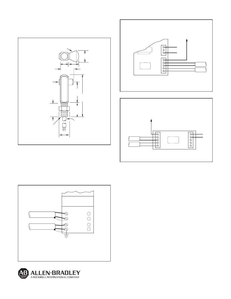
WIRING DIAGRAMS
1
2
3
4
PLUGĆIN
CONTROL MODULE
22 SERIES 4000
CONTROL BASE
47CN4 AND 47SN1
RECEIVERS
40CA4 AND 40SA1
LED SOURCES
WHT
RED
RED
BLK
SH
SH
GROUND THIS
TERMINAL
Notes:
1. Ground receiver housing (machine ground O.K.)
2.Ground terminal 4.
WIRING DIAGRAMS
OPEN COLLECTOR (NPN) CURRENT SINK
OUTPUT TO POWER EXTERNAL LOADS
OR TO #61-2124 OUTPUT BASE
L1
L2
OUT
1
2
3
SERIES
5000
#60–2120 BASE
120VAC
RECEIVER
LED SOURCE
BLK
RED
RED
WHT
CONNECT ALL SHIELDS TO TERMINAL PS (-)
PS( -)
WITH UNIVERSAL FUNCTION BASE #60–2120
OUT
1
2
3
PS (-)
SERIES
5000
PS (+)
PS (-)
OUT
1
( + )
( - )
24VDC
#60-2123
OPEN COLLECTOR (NPN) CURRENT SINK
OUTPUT TO POWER EXTERNAL LOADS
OR TO #61-2124 OUTPUT BASE
OUTPUT
RECEIVER
BLK
RED
#60–2123 BASE
CONNECT ALL SHIELDS TO TERMINAL PS (-)
RED
WHT
LED SOURCE
WITH MULT–MODULE FUNCTION BASE #60–2123
ALIGNMENT
Set the amplifier to the light operate mode. Adjust the sensitivity
to the maximum setting, turning the sensitivity potentiometer clock-
wise. Aim the light source at the receiver until the alignment indicator
on the amplifier turns on.
To be certain that the beam is centered, sweep the receiver at the
light source in the horizontal plane and determine the position where
the alignment indicator turns on and then off. Do the same in the verti-
cal plane. Set the beam halfway between both positions.
It may be necessary to reduce the sensitivity to a lower setting for
transparent or translucent materials or to detect objects smaller that
the effective beam.
Publication PA–9200(A)
November 1992
Supercedes Publication PA–7913