Rockwell Automation 42GNC_NF_NL_NP_NR_NU SmartSight DeviceNet PHOTOSWITCH Photoelectric Sensors User Manual
Page 3
3
User Interface
Using an instrument screwdriver, open the top cover of the sensor to gain access to the user interface
panel. This panel contains a pushbutton, node-address switches, and LED indicators for configuring and
viewing the sensor’s operation and status. A more complete description of each item is described below.
SmartSightt Sensor—Top View Detail
Node
Address
Pushbutton
A single momentary pushbutton, labeled LRN, is used to “teach” the sensor the application presented to it.
Refer to the Self-Teach in this document for complete instructions on using this feature.
Selector Switches
Two selector switches are provided for setting the sensor node address on the network. Possible addresses
range from 063. The node address may also be set over the network using the RS Networx configuration
tool.
LED Indicators
Three LED indicators are provided to indicate a variety of conditions making it easy for installation and
troubleshooting. The function of each is described in the table below. The LEDs also work together as
indicated on page 5 when used in the self-teach mode.
Table 1. LED Function
Label
Color
State
Status
Output
Yellow
ON
Target detected
Margin
Orange
OFF
Margin < 2.5
ON
Margin 2.5
Network
Red/Green
OFF
Sensor not powered
Green ON Steady
Sensor active and allocated by master
Green Flashing
Sensor active but not allocated by master
Red Flashing
Minor correctable fault (baud rate)
Red ON Steady
Major fault (possible duplicate address)
Note
: LED indicators are used during the Self-Teach operation of the sensor. Refer to the Self-Teach
section for complete instructions on using this feature.
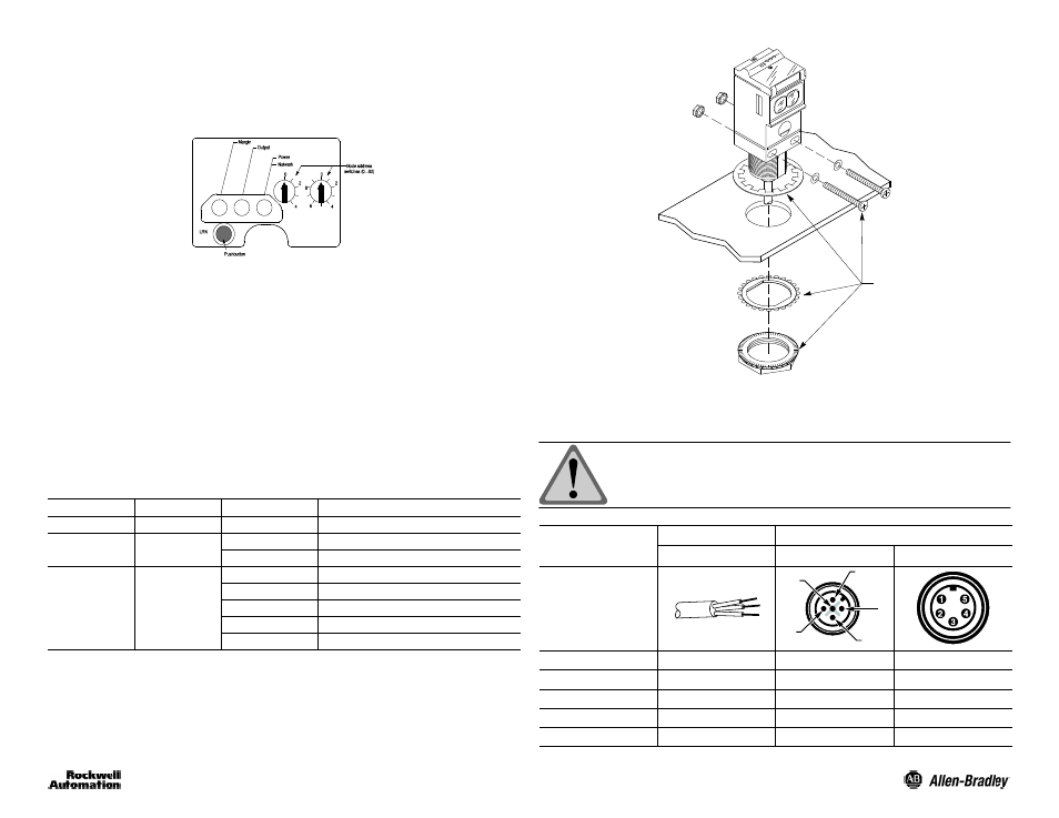
Mounting the Sensor
Securely mount the sensor on a firm, stable, surface or support using one of the many mounting brackets
available from Rockwell Automation/Allen-Bradley. The sensor is supplied with hardware kit #129--130
which contains a plastic mounting nut, lock washer, 2 M5 x 0.8 x 53 screws and nuts. Excessive vibration or
shifting may cause intermittent operation of the sensor.
Hardware Kit
(Supplied)
Wiring the Sensor
Models of SmartSight are available in one of three different connection types as identified in the following
table. Rockwell Automation/Allen-Bradley recommends the use of the 1485R Series of cordsets and
patchcords on the quick-disconnect models.
ATTENTION: All external wiring should conform to the National
Electric Code and all applicable local codes.
Designation
Lead Color
Cordset Pin Assignment
2 m Cable
5-Pin Micro QD
5-Pin Mini QD
5
4
3
1
2
V+
Red
2
2
V--
Black
3
3
CAN +
White
4
4
CAN --
Blue
5
5
Drain
Bare
1
1