Rockwell Automation 20P PowerFlex DC Drive - Frame A Field SCR/Dual Diode Bridge Module User Manual
Page 12
12
PowerFlex® DC Drive - Frame A Field SCR/Dual Diode Bridge Module
Step 6: Install the New
Field SCR/Dual Diode
Bridge Module
Install the new Field SCR/Dual Diode Bridge module in reverse order of
removal as detailed in Step 5:
Remove the Existing Field SCR/Dual Diode
.
1. Apply thermal grease to the bottom of the Field SCR/Dual Diode
Bridge module before securing it to the heatsink.
2. Verify that the field circuit wires are connected to the correct location
on the Field SCR/Dual Diode Bridge module.
Step 7: Install the Pulse
Transformer and Switching
Power Supply Boards
• Install the Pulse Transformer and Switching Power Supply boards in
reverse order of removal as detailed in Step 4:
Transformer and Switching Power Supply Boards on page 6
Step 8: Install the Control
EMI Shield and Control
Board
• Install the Control EMI Shield and Control board in the reverse order of
removal as detailed in Step 3:
Remove the Control EMI Shield and
.
ATTENTION: Thermal grease must be applied to the bottom
of the Field SCR/Dual Diode Bridge module before securing
them to the heatsink or damage to the drive may occur.
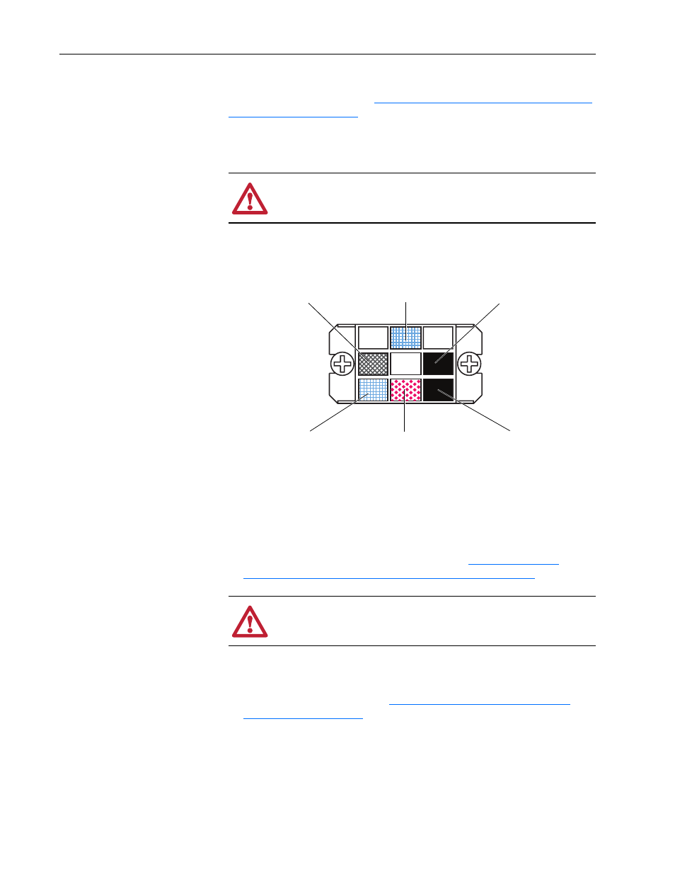
Blue wire from 2D1
on Field board
Red wire from 2C1
on Field board &
Thin Red Wire from
XP on Pulse
Transformer board
Black wire from
2V1 on Field board
Brown or Green wire
from 2U1 on Field board
Blue wire from XP on
Pulse Transformer board
Black wire from XP on
Pulse Transformer board
ATTENTION: Each gate lead cable must be connected to the
exact connector from which it was removed on the Pulse
Transformer circuit board or damage to the drive may occur.