Step 9: document the change, Related documentation, Document the change – Rockwell Automation 20P, 23P PowerFlex DC Drive and SAR Control Circuit Board Installation Instructions User Manual
Page 16
Publication 20P-IN004B-EN-P
16
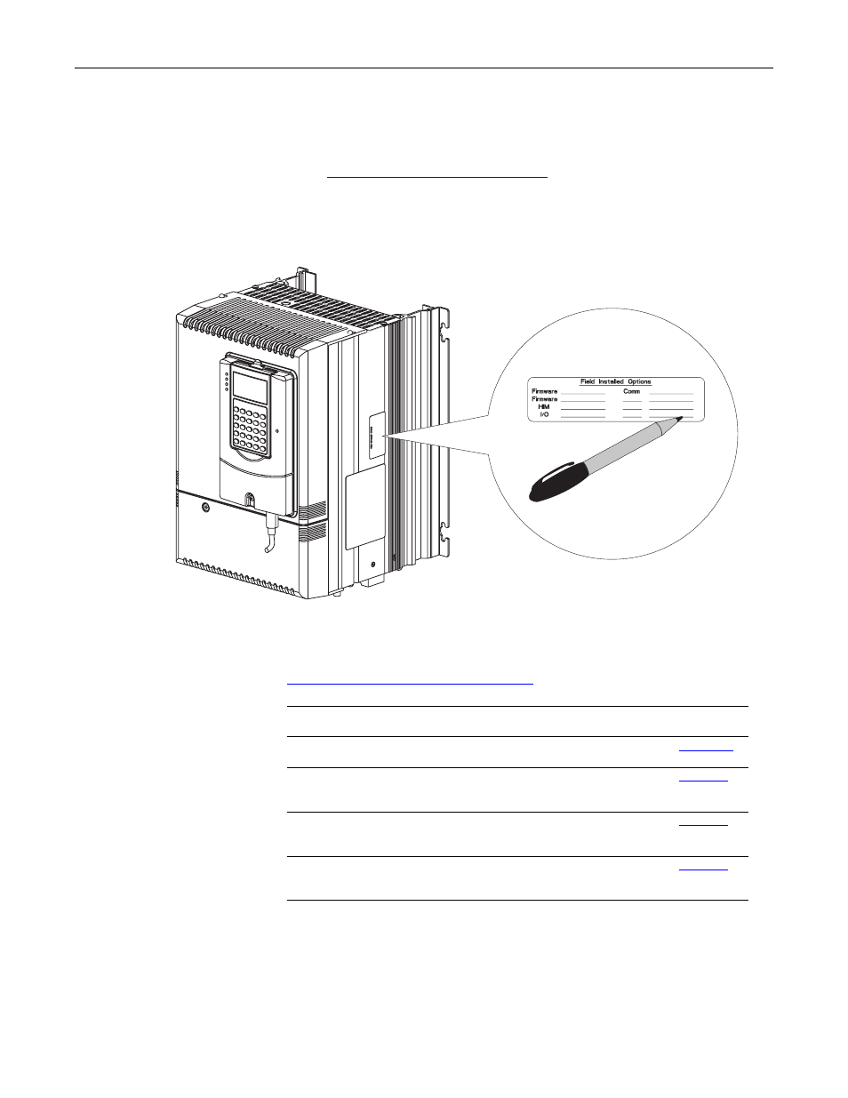
Step 9: Document the
Change
1. Record the installation of the new control board and date of installation on
the field installed option label on the side of the drive (as shown below).
2. Replace the drive covers in the reverse order of removal as described in Step
Remove the Drive Covers on page 3
3. Install DPI cable (if present).
4. Down load the parameter configuration back into the drive.
Related Documentation
Allen-Bradley publications are available on the internet at
.
Frame A Shown
For . . .
Read this document
Publication
Number
In-depth information regarding the
operation of PowerFlex Digital DC drives
User Manual - PowerFlex Digital DC Drives
In-depth information regarding the
installation and wiring of the resolver
feedback option module
Installation Instructions - PowerFlex DC
Drive Resolver Feedback Option Module
In-depth information regarding the
installation and wiring of the I/O
expansion circuit board
PowerFlex DC Drive Analog and Digital
I/O Expansion Circuit Board
In-depth information regarding the
installation and wiring of the115V AC to
24V DC converter board
PowerFlex DC Drive 115V AC to 24V DC
I/O Converter Circuit Board