Remove the switching power supply circuit board – Rockwell Automation 23P PowerFlex DC Stand-Alone Regulator (SAR) Switching Power Supply Circuit Board User Manual
Page 7
Rockwell Automation Publication 23P-IN002A-EN-P - June 2011
7
Step 5: Remove the
Switching Power
Supply Circuit
Board
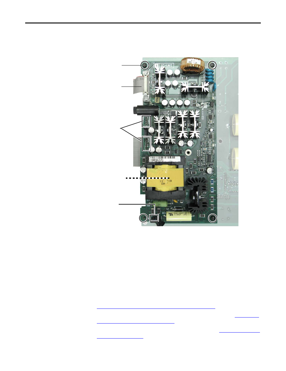
1. Remove the stand-off mounting screw (1) next to the XR ribbon cable connector on
the power interface circuit board.
2. Label and disconnect the plug at connector XUV.
3. Remove the mounting screws (4).
4. Carefully pull the two boards apart, pulling the XSW and XSW1 plugs on the
switching power supply circuit board out of the pins on the power interface circuit
board.
5. Label and disconnect the XA ribbon cable, and save for reassembly.
6. Save the power interface circuit board for reassembly.
7. Dispose of the switching power supply circuit board properly.
Step 6: Install the
New Switching
Power Supply
Circuit Board and
Reassemble the
SAR
1. Install the new switching power supply circuit board in reverse order of removal. See
Remove the Switching Power Supply Circuit Board on page 7
2. Install the power interface circuit board in reverse order of removal. See
Power Interface Circuit Board on page 5
.
3. Install the control circuit board in reverse order of removal. See
.
Mounting Screws (4)
Tightening torque:
1.0 N•m (8.9 lb•in)
XUV
Stand-off mounting
screw (1) is removed at
XR on the power
interface circuit board
IMPORTANT
XSW and XSW1
plugs on the
switching power
supply circuit board
fit into the pins on
the power interface
circuit board.
XA