Rockwell Automation 23P PowerFlex DC Stand-Alone Regulator (SAR) Field Circuit Board User Manual
Page 7
Rockwell Automation Publication 23P-IN003A-EN-P - June 2011
7
2. Label and remove the XFCD ribbon cable from its hoop harness. Cut the plastic tie at
the plug and disconnect from the field circuit board. Save for reassembly.
3. Remove the mounting screws (4, long) to the field power terminals.
4. Remove the mounting screws (3, medium) from the dual diode module.
5. Remove the mounting screws (3, medium) from the field SCR module.
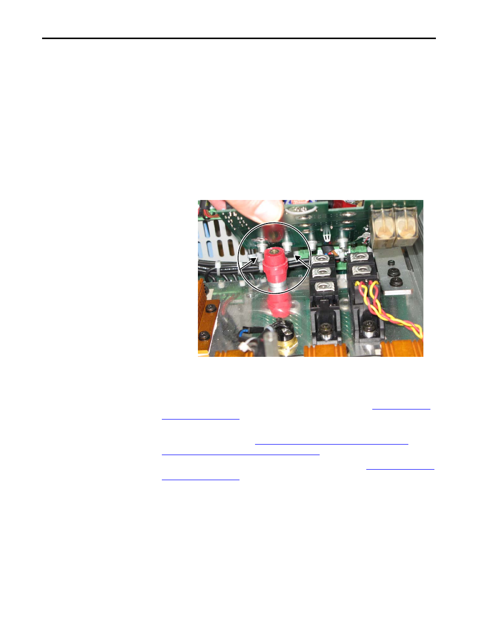
6. Remove the mounting screw (1, short) for the transducer cable to the glastic
stand-off. Save the transducer cable for reassembly.
7. Remove the stand-off from the heatsink. Be sure to also remove the small washer that
is used with the stand-off.
8. Lift the front edge of the field circuit board up at an angle and carefully pass the
mounting screw wells over the glastic spacer stack, and remove the field circuit board.
9. Dispose of the field circuit board properly.
Step 6: Install the
New Field Circuit
Board and
Reassemble the
SAR
1. Install the new field circuit board in reverse order of removal. See
.
2. Install the power interface circuit board and switching power supply circuit board in
reverse order of removal. See
Remove the Power Interface Circuit Board and
Switching Power Supply Circuit Board on page 5
3. Install the control circuit board in reverse order of removal. See
.
IMPORTANT
Lift the Front of
the Field Circuit
Board at an
Angle Until you
can Pull the
Power Terminal
Mounting
Screw Wells
Over the Glastic
Spacer Stack.