Wiring diagram, The field of view of the 45mla is 3.2, For use in nfpa 79 applications only. important – Rockwell Automation 45MLA Measuring Light Array Sensors User Manual
Page 3
3
Vertical Alignment
1. Beginning with the two arrays parallel to each other, slide the
receiver down and note the point at which the red LEDs turn
ON on both arrays. This indicates that the receiver is no longer
in line with the emitter.
2. Slide the receiver back upwards until the red LEDs turn OFF
and the green LED on the receiver turns ON. This indicates that
the two arrays are aligned.
3. Continue to slide the receiver upwards, noting the point at
which the green LED turns OFF, and the two red LEDs turn ON,
again indicating misalignment.
4. For vertical centering, position the receiver halfway between
the two points at which the red LEDs turn OFF.
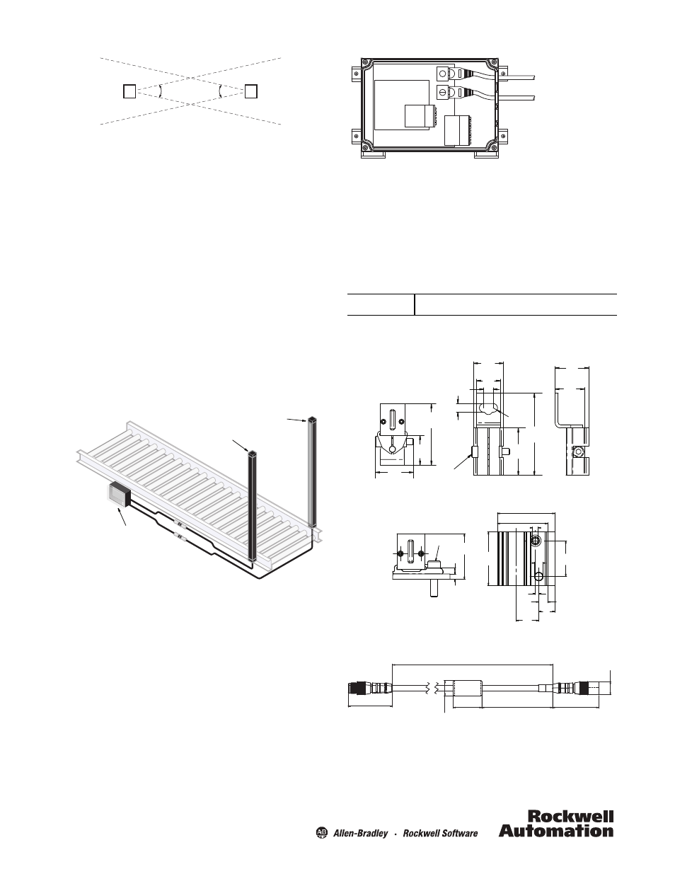
Wiring Diagram
The 45MLA is a “Three Box System”—every setup consists of an
emitter array, a receiver array, and an external controller.
The 45MLA arrays feature an M12, 8-pin female QD which
connects to the connecting cable 445L-AC9RJx (x = 3, 5, or 8
meter length). The other end of the 445L connecting cable has an
RJ45 connector which plugs into the ports on the controller. The
emitter plugs into the top port, marked with the white dot. The
receiver plugs into the lower port, marked with the blue dot. The
445L connecting cable comes with both blue and white markers
at each end. It is recommended to remove the markers that do
not correspond to the array pigtail marker.
3.2°
3.2°
The field of view of the 45MLA is 3.2°
Receiver Array
Emitter Array
45MLA Controller
All electrical connections are made via the 45MLA-CTRL
controller.
Note: Cascading light array systems can consist of two or three
light array pairs. The last pair must be a standard array pair
and the first (and middle) pairs must be cascadable. A
total system can be no more than 10 m (32.8 ft) in length
from the controller to the end of the last array and cannot
exceed 254 total beams.
Adjustable Bracket 445L-AF6143
(4 pieces included) [mm (in.)]
Flat Bracket 445L-AF6145 (sold separately) [mm (in.)]
Cascadable Array Extension Patchcord 445L-AC8PCx
Emitter connecting cable
Receiver connecting cable
For use in NFPA 79 applications only.
IMPORTANT
18.9
(0.74)
15
(0.59)
6
(0.24)
2.8
(0.11)
5.5 (0.22)
M4 x 16
30
(1.18)
52
(2.05)
38.7
(1.53)
18.7
(0.73)
24
(0.95)
21.4
(0.84)
18.7
(0.73)
32 (1.26)
28 (1.10)
M4
20
(0.79)
4.8
(0.19)
dia.
1.9
(0.08)
4.9
(0.19)
12.7
(0.50)
8.9
(0.35)
30
(1.18)
25.5
(1.00)
M4 x 16
3.3
(0.13)
3
(0.12)
Length, 1 or 3 m (3.28 or 9.8 ft); tolerance 0/+50 mm
50.2
(1.98)
17
(0.67)
Dia.
32.2
(1.27)
80
(3.15)
51.3
(2.02)
15 (0.59)
Dia.