Rockwell Automation 42EF LaserSight RightSight Photoelectric Sensors User Manual
Page 3
3
Notes Regarding the Teach Function:
S
The light condition (target for diffuse, reflector for retroreflective sense mode) must
be presented first followed by the dark condition (no target for diffuse, target for
retroreflective sense mode).
S
A flashing green PWR/STAB LED indicates an unstable application condition (little
contrast between light and dark conditions). This can be caused by improper
alignment to the reflector (retroreflective sense mode) or due to a highly reflective
background behind the target being sensed (diffuse sense mode). In this case of a
diffuse sense mode, it may be necessary to use a background suppression sense
mode in the application. A second cause can be due to excessive reflected light
being returned to the sensor.
Manually Adjustable Versions
LaserSight RightSight photoelectric sensors with no teach function contain a manual
adjustment knob for adjusting the sensors sensitivity level. This knob sets sensitivity
from low (counterclockwise) to high (clockwise). Follow the steps below to configure the
sensor for your specific application.
Diffuse Sense Mode (Light Operate)
1. Ensure that the sensor is securely mounted and wired. The green LED will be
illuminated indicating that power is applied to the sensor. Turn sensitivity adjustment
fully clockwise.
2. Visually align the sensor on the target until the yellow OUT LED turns ON.
3. To be certain that the beam is centered, it is required to sweep the sensor in the
horizontal and vertical plane and determine at what position the yellow OUT LED
turns ON and then OFF. Set the sensor halfway between both positions.
4. Remove the object in front of the sensor and eliminate any background signals by
turning down the sensitivity adjustment, (if such background signals exist). Replace
the object and verify that the yellow OUT LED turns ON and that the green
PWR/STAB LED does not flash.
Transmitted Beam Versions (no adjustment)
1. Ensure that the sensor is securely mounted and wired. The green LED will be
illuminated indicating that power is applied to the sensor.
2. Visually align the emitter and receiver units until the yellow OUT LED turns OFF.
Also verify that the green PWR/STAB LED does not flash.
3. To be certain that the beam is centered, it is required to sweep the emitter or
receiver in the horizontal and vertical plane and determine at what position the
yellow OUT LED turns ON and then OFF. Set the sensor halfway between both
positions.
4. Break the beam with the object to be detected and check if the yellow OUT indicator
turns ON. If this does not happen, affix an aperture to both the emitter and receiver
or increase the distance between the emitter and receiver. Restore the light beam by
removing the object and check if the yellow OUT LED turns OFF again and that the
green PWR/STAB LED does not flash.
Short-Circuit Protection
RightSight photoelectric sensors provide short-circuit protection (SCP) on the output
leads. This feature is intended to protect the sensor from damage in the event that the
output load is shorted to ground. If this condition does occur, the SCP will activate and
the both the red and green LED indicators will flash until the source of the short is
removed. The SCP limits are set to approximately 100 mA over the entire voltage
range.
Notes Regarding Reflectors
1. Maximum sense range for polarized retroreflective sense modes is based upon a
92--118 microcube reflector. Performance will vary with other reflector types.
2. Polarized retroreflective sense mode may exhibit white paper response between 50
and 300 mm.
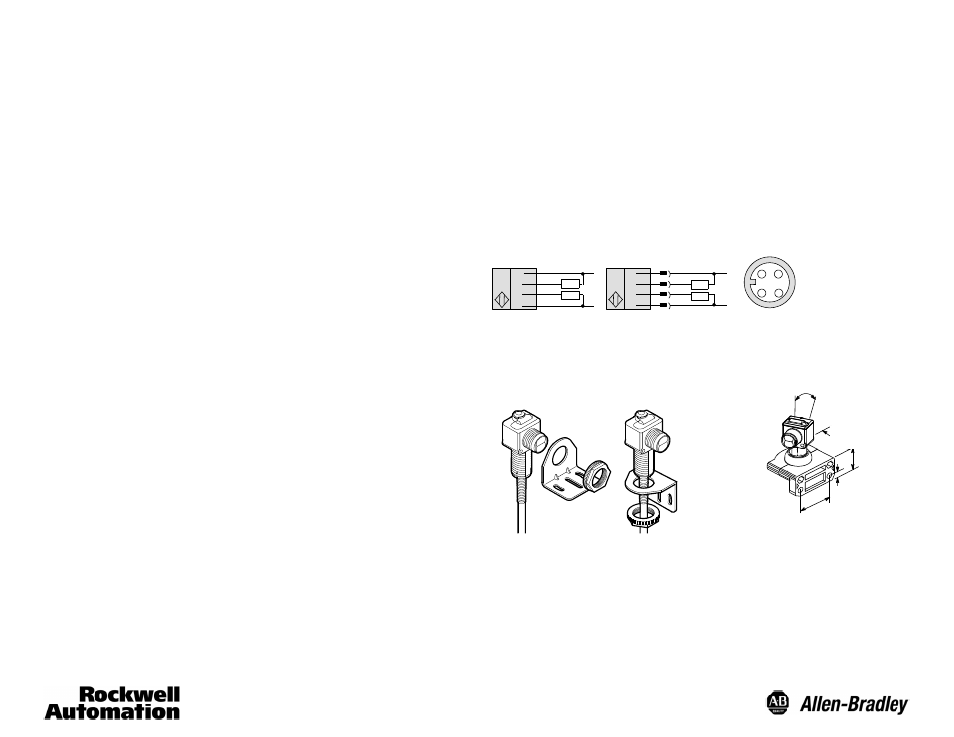
Wiring Diagrams
+
--
Brown
Blue
White
Black
+
--
1
2
4
3
Cable
Quick-Disconnect
Brown
White
Black
Blue
DC Micro
Load
Load
Load
Load
1
3
2
4
For Allen-Bradley programmable controller compatible interface, refer to publication 42--2.0.
All wire colors on quick-disconnect models refer to Allen-Bradley 889D cordsets.
Accessories
50.08
(2.0)
28.6
(1.125)
10_Adjustment in
Each Direction
Right Angle Bracket #60--2657
Swivel/Tilt Bracket #60--2649
57.15
(2.25)
7.95
(0.31)
Notes
1. Damage may occur to sensor housing if torque above 20in-lb is applied to the 18mm locknut.
2. Optional mounting kit (60--2716) comes with two 75012--025--01, one 75012--097--01 locknut, internal tooth
star washer, and screws/nuts for through-hole mounting.