Remove the field scr module and dual diode module – Rockwell Automation 23P PowerFlex DC Stand-Alone Regulator (SAR) Field SCR Module and Dual Diode Module User Manual
Page 8
8
Rockwell Automation Publication 23P-IN004A-EN-P - June 2011
Step 6: Remove the
Field SCR Module
and Dual Diode
Module
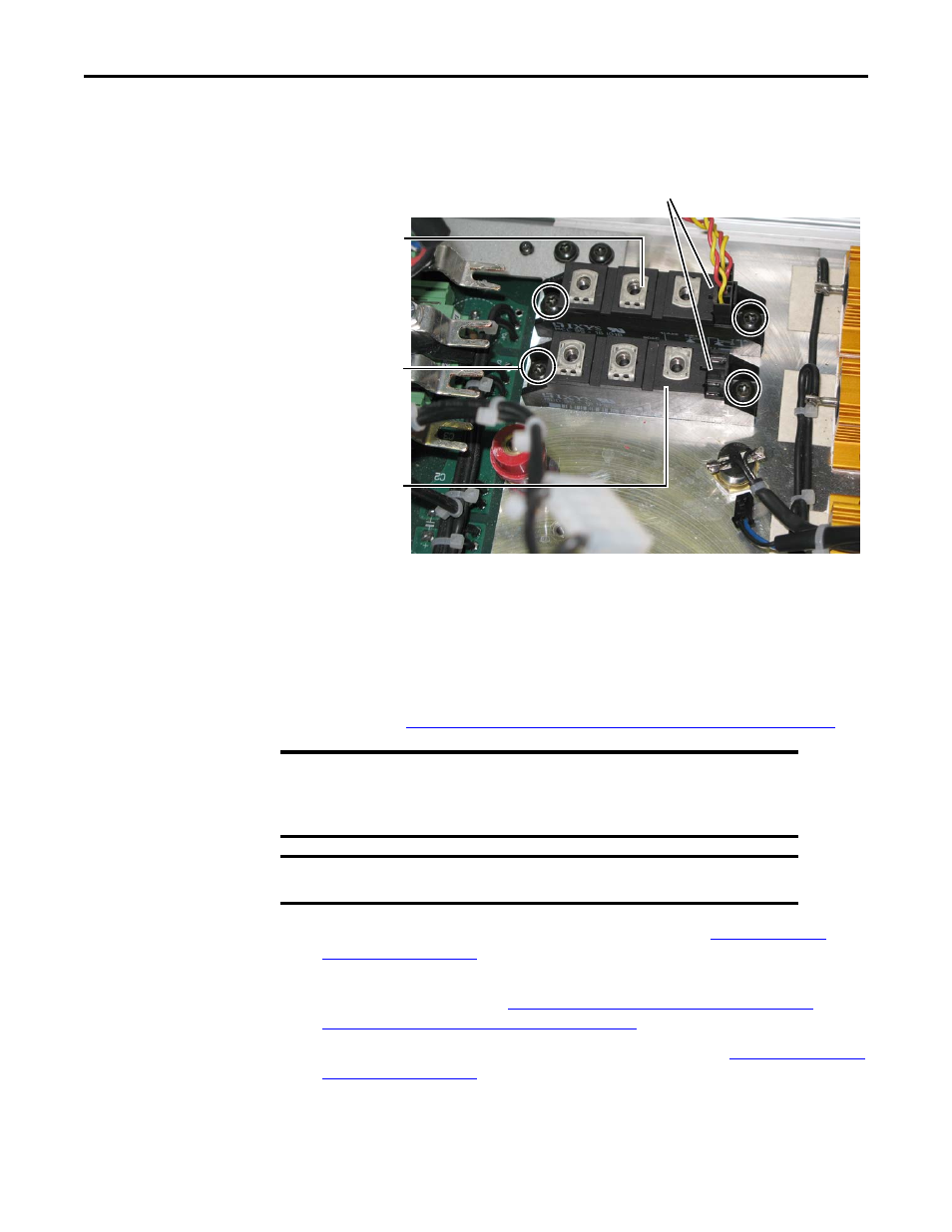
1. Remove the mounting screws (2) from the field SCR module.
2. Remove the mounting screws (2) from the dual diode module.
3. Unplug the red and yellow gate lead wire harnesses (2) from the field SCR module,
and save for reassembly.
4. Dispose of the field SCR module and dual diode module properly.
Step 7: Install the
New Field SCR
Module and Dual
Diode Module and
Reassemble the
SAR
1. Install the new field SCR module and new dual diode module in reverse order of
removal. See
Remove the Field SCR Module and Dual Diode Module on page 8
.
2. Install the field circuit board in reverse order of removal. See
.
3. Install the power interface circuit board and switching power supply circuit board in
reverse order of removal. See
Remove the Power Interface Circuit Board and
Switching Power Supply Circuit Board on page 5
4. Install the control circuit board in reverse order of removal. See
.
Field SCR Module
Dual Diode Module
Module Mounting
Screws
(2 each module)
Tightening torque:
2.5…4 N•m
(22…35.4 lb•in)
Gate Leads Facing
Toward Resistors
IMPORTANT
Thermal grease must be applied to the bottom of the field SCR module
and dual diode module before securing them to the heatsink. Clean the
surface of the heatsink and the modules with isopropyl alcohol, then
apply a thin coat of thermal grease to the modules.
IMPORTANT
Verify that the modules are installed with the gate leads in the proper
position, facing towards the resistors.