Rockwell Automation 20Y PowerFlex Active Front End in IP20 2500 MCC Style Encl. Fr. 10 Bus Splice Kit User Manual
Page 9
Rockwell Automation Publication 20Y-IN003A-EN-P - September 2014
9
PowerFlex Active Front End in IP20 2500 MCC Style Enclosure Frame 10 Bus Splice Kit
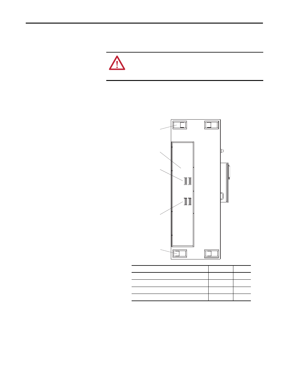
Step 5: Attach both enclosures using the air barrier panels and hardware
supplied in the barrier kit (catalog number SK-Y1-MCCBARRIER).
a.
Note the air barrier panel orientations in this figure, position the
barrier panels onto the left side of the AFE enclosure, and attach the
panels using the supplied hardware (see table below).
b. Attach the left side of the AFE enclosure to the right side of the
adjacent enclosure.
Torque fasteners to 55.0 in
•lb (6.2 N•M) when fastening the
enclosures together.
ATTENTION: The barrier kit must be used between the enclosures being
attached together to maintain proper air flow within each individual enclosure.
Failure to use the barrier kit can result in overheating that can cause equipment
damage.
SK-Y1-MCCBARRIER Kit Supplied Parts/Hardware
Part Number
Quantity
PowerFlex 755 High HP Cabinet Barrier Panel, Rear
PN-204975
1
Cabinet Barrier Panel, Upper
PN-160374
2
Cabinet Barrier Panel, Lower
PN-160385
2
Screw, Hex Flange HD, Taptite, M6 x 20 mm
29171-640-02
22
PN-204975
Upper Air Barrier Panel
PN-160374
2 Places
Lower Air Barrier Panel
PN-160385
2 Places
DC+ Bus
Location
DC– Bus
Location
Barrier Panels on Left Side of AFE Enclosure