Step 4: wiring the kit – Rockwell Automation 20L-RESPRE-A1 PowerFlex 700L Frame 3A and 3B Input Filter Precharge Resistor Kit User Manual
Page 7
PowerFlex® 700L Frame 3A and 3B Input Filter Precharge Resistor Kit (20L-RESPRE-A1)
7
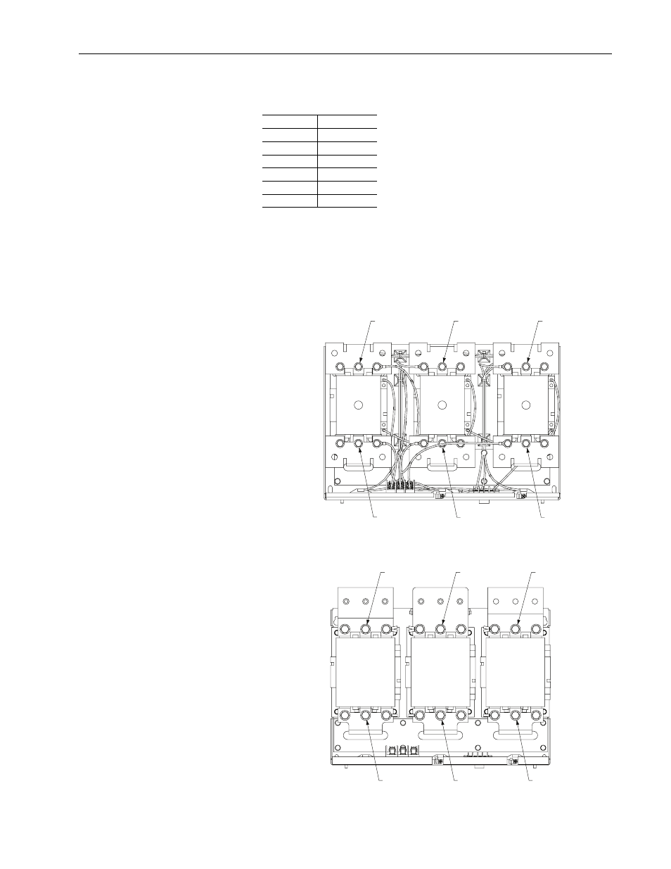
Step 4: Wiring the Kit
Connect the kit’s resistors in parallel with the existing precharge resistors in
the input filter. Wire the kit as follows:
On the kit side, tighten the screws to the torque shown in the drawings of
Step 3. Use tie-wraps to bundle the wiring. Route the wiring through the
grommet hole shown in the drawing on page 5. On the input filter side, use
the existing M8 hex head screws on the contactors as shown in the drawings
below and ring lugs (not provided) for wiring connections. Tighten the
screws on the contactors to 14.9 N-m (132 lb.-in.).
From Kit
To Input Filter
TB5-1
K1A-L2
TB5-2
K1B-L2
TB5-4
K1C-L2
FU13
K1A-T2
FU14
K1B-T2
FU15
K1C-T2
L1
L2
L3
T1
T2
K1A
K1B
K1C
T3
L1
L2
L3
T1
T2
T3
L1
L2
L3
T1
T2
T3
To Kit TB5-1
To Kit TB5-2
To Kit FU14
To Kit TB5-4
To Kit FU13
To Kit FU15
Frame 3A
L1
L2
L3
T1
T2
K1A
T3
L1
L2
L3
T1
T2
K1B
T3
L1
L2
L3
T1
T2
K1C
T3
Frame 3B
To Kit TB5-1
To Kit TB5-2
To Kit TB5-4
To Kit FU13
To Kit FU14
To Kit FU15