Rockwell Automation 20P PowerFlex DC Drive - Frame B Field Dual Diode Module User Manual
Page 13
PowerFlex® DC Drive - Frame B Field Dual Diode Module
13
Step 5: Install the Field
Board and New Field Dual
Diode Module
Install the Field board and new Field Dual Diode module in reverse order of
removal as detailed in Step 4:
Remove the Field Board and Existing Field
.
•
Apply thermal grease to the bottom of the Field Dual Diode module
before securing it to the heatsink.
•
Tightening torque for the screws connecting the Field Dual Diode
module to the heatsink and the screws connecting the Field board to the
Field SCR and Dual Diode modules is 2.5…4.0 N•m (22…35 lb•in).
Step 6: Install the Pulse
Transformer and Switching
Power Supply Boards
Install the Pulse Transformer and Switching Power Supply boards in reverse
order of removal as detailed in Step 3:
Remove the Pulse Transformer and
Switching Power Supply Boards on page 5
.
•
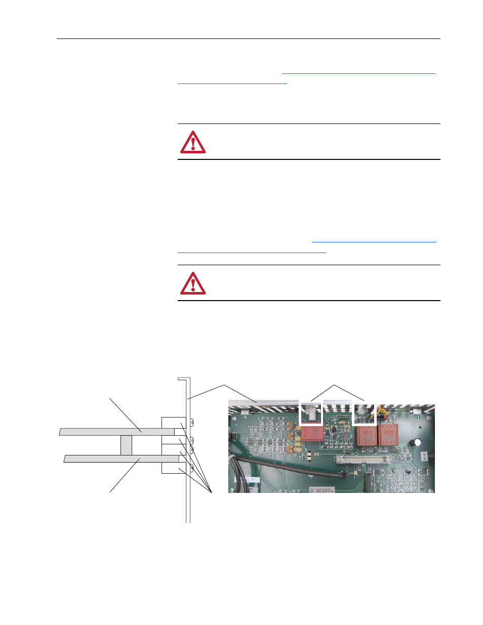
Verify that the four plastic board stabilizers mounted on the top air flow
plate are placed one on either side of each of the Pulse Transformer and
Switching Power Supply boards.
ATTENTION: Thermal grease must be applied to the bottom
of the Field Dual Diode module before securing it to the heatsink
or damage to the drive may occur.
ATTENTION: Each gate lead cable must be connected to the
exact connector from which it was removed on the Pulse
Transformer circuit board or damage to the drive may occur.
One plastic stabilizer should be on either side of each board
Air flow plate
Plastic
stabilizers
Top view of Pulse Transformer board
Side cut-away view
Pulse Transformer board
Switching Power Supply board