Identifying the relay, Replacing the relay – Rockwell Automation SK-G9-RELAY-F9 700 Phase Monitor Relay - Frame 9 User Manual
Page 2
2
Rockwell Automation Publication 20B-IN027A-EN-P - March 2011
PowerFlex 700 Phase Monitor Relay Replacement
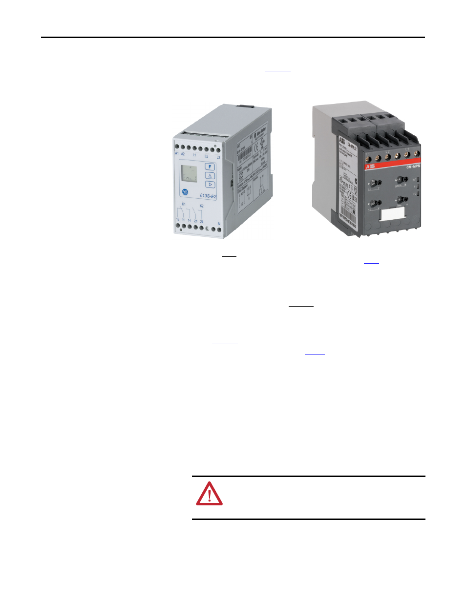
Identifying the Relay
Two types of Phase Monitor Relays are used in Frame 9 drives depending on the
date of manufacture. Refer to
and determine the relay type currently
installed in your drive. Next, locate the corresponding replacement procedure.
Figure 1 - Relay Identification
Replacing the Relay
Type A - Drives Manufactured before January 20, 2011
1.
Verify that all power to the drive has been removed.
2.
Using
, verify that the relay installed in your drive matches “Type
A.” If not, refer to the procedure on
.
3.
Locate terminals L1, L2 and L3 on the existing relay. Verify that the wires
connected to each terminal are labeled correctly, then remove the wires.
4.
Cut and insulate the two wires connected to A1 and A2. These wires will
not be used with the replacement relay. Ensure that the wire ends are well
insulated using wire nuts and tape. Secure the loose ends to the wire
harness.
5.
The wires just cut and insulated are routed to the “120V” and “N”
terminals of TB-9. Trace these wires back to TB-9 and disconnect. Insulate
the ends and secure to the wire harness.
6.
Remove the wire connected to terminal 21 of the relay. Relabel this wire
“25.”
Type A
Drives Manufactured before January 20, 2011
(see below)
Type B
Drives Manufactured January 20, 2011 and after
ATTENTION: To guard against possible equipment damage and/
or personal injury, ensure that the wires previously disconnected
from the relay and TB-9 are thoroughly insulated (using wire nuts
and tape) and secured to the wire harness.