Step 6: install the new scr modules – Rockwell Automation 20P PowerFlex DC Drive - Frame B SCR Modules User Manual
Page 17
PowerFlex® DC Drive - Frame B SCR Modules
17
Step 6: Install the New
SCR Modules
Install the new SCR Modules in reverse order of removal as detailed in Step
5:
Remove the Existing SCR Modules on page 11
Important Notes for installation:
•
Thermal grease must be applied to the bottom of each SCR Module
before securing it to the heatsink.
•
Use the following table to determine the proper tightening torque for the
SCR Modules installed on the heatsink:
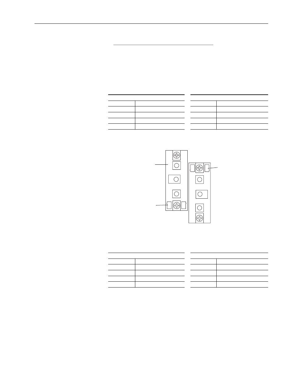
•
Use the following orientation for installing the SCR Modules:
•
Use the following table to determine the proper tightening torque for the
bus bars connected to the SCR Modules:
230V AC Input
460V AC Input
Part Number
Final Torque
Part Number
Final Torque
SK-20P-S7F48 2.5…4 N•m (22…35.4 lb•in)
SK-20P-S7F78 2.5…4 N•m (22…35.4 lb•in)
SK-20P-S7F49 4.5…5.5 N•m (40…48.7 lb•in)
SK-20P-S7F79 4.5…5.5 N•m (40…48.7 lb•in)
SK-20P-S7F42 4.5…5.5 N•m (40…48.7 lb•in)
SK-20P-S7F41 4.5…5.5 N•m (40…48.7 lb•in)
SK-20P-S727F 4.5…5.5 N•m (40…48.7 lb•in)
SK-20P-S737F 4.5…5.5 N•m (40…48.7 lb•in)
230V AC Input
460V AC Input
Part Number
Final Torque
Part Number
Final Torque
SK-20P-S7F48 4.5…5.5 N•m (40…48.7 lb•in)
SK-20P-S7F78 4.5…5.5 N•m (40…48.7 lb•in)
SK-20P-S7F49 4.5…5.5 N•m (40…48.7 lb•in)
SK-20P-S7F79 4.5…5.5 N•m (40…48.7 lb•in)
SK-20P-S7F42 11…13 N•m (97.4…115 lb•in)
SK-20P-S7F41 11…13 N•m (97.4…115 lb•in)
SK-20P-S727F 11…13 N•m (97.4…115 lb•in)
SK-20P-S737F 11…13 N•m (97.4…115 lb•in)
1
2
3
2
1
3
Gate leads at top
Gate leads at bottom
This SCR Module
only present in
regenerative drives.