3mounting, Wiring, Accessories micron conversions – Rockwell Automation 45BRD Analog Laser Sensor User Manual
Page 3
3
Mounting
Securely mount the sensor on a firm, stable surface or support for
reliable operation. A mounting which is subjected to excessive
vibration or shifting may cause intermittent operation. The
following mounting brackets are available for installation
convenience and sensor protection. Once securely mounted, the
sensor can be wired per the attached wiring diagram.
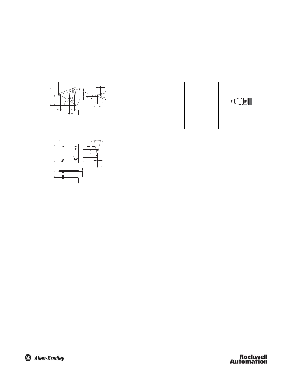
Mounting Bracket Dimensions—mm (inches)
45BPD-BKT1
45BPD-BKT2
Wiring
The 45BRD photoelectric sensor is available with a micro quick-
disconnect for ease of installation and maintenance. The connector
can be rotated up to 270º to accommodate the installation of the
sensor and its associated wiring. Rockwell Automation
recommends the use of the 889 Series of cordsets and patchcords
for quick disconnect model sensors. All external wiring should
conform to the National Electric Code and all applicable local
codes.
48.5 (1.9)
4.3 (0.169)
4.2
(0.165)
10.5 (0.41)
22 (0.86)
24˚
4.3 (0.169)
10.5
(0.41)
50˚
30
(1.18)
50.97
(2.0)
4.3
(0.169)
2
(0.07)
21.2
(0.83)
13.9
(0.54)
58
(2.28)
4.3
(0.169)
24˚
4.3 (0.169)
14.85 (0.58)
17
(0.66)
23.8
(0.93)
7 x M4
38.2 (1.5)
8.5
(0.33)
65 (2.55)
Application Notes
1. The sensor should be powered for approximately 5 minutes for
maximum precision.
2. The sensor indicator LED is green when the unit is powered.
3. The sensor indicator LED will be red if the lens becomes soiled
or contaminated.
4. The precision of the sensor is dependent on the combined
errors of linearity, resolution and temperature drift.
Accessories
Micron Conversions
Description
Cat. No.
2m (6.5ft) Micro
QD Cordset
889D-F4EC-2
Mounting Bracket
45BPD-BKT1
Protective
Mounting Bracket
45BPD-BKT2
1
μm
=
0.001 mm
1
μm
=
0.000039 inches
25.4
μm
=
0.001 inches (one thousandth)
20
μm
=
0.00079 inches (0.79 thousandths)