Calibration offset function, Outline of function, Y=ax+b – Yamato Scientific DN410H Constant Temperature Ovens User Manual
Page 72
22
Calibration Offset Function
Outline of Function
In the controller, the relationship between the temperature
T detected by the sensor and the display temperature of
the operation panel D is expressed by the equation of the
line which passes the two points (T
0
, D
0
) and (T
S
, D
S
)
shown in Fig. 1.
Here, T
0
is the sensor detecting temperature when the chamber
central temperature becomes the zero adjusting temperature
(normally room temperature is adopted) D
0
at the time of no load, T
S
is the sensor detecting temperature when the chamber central
temperature becomes the span adjustment temperature (normally
working maximum temperature is adopted) D
S
at the time of no load
in the same way.
As it is clear from the facts above, conforming of the chamber central
temperature and the display temperature is guaranteed only when
there is no load and at two points shown above. In other words, it is
possible for a temperature measured at a point in the chamber does not conform to the display temperature
of the operation panel at a voluntary temperature without load.
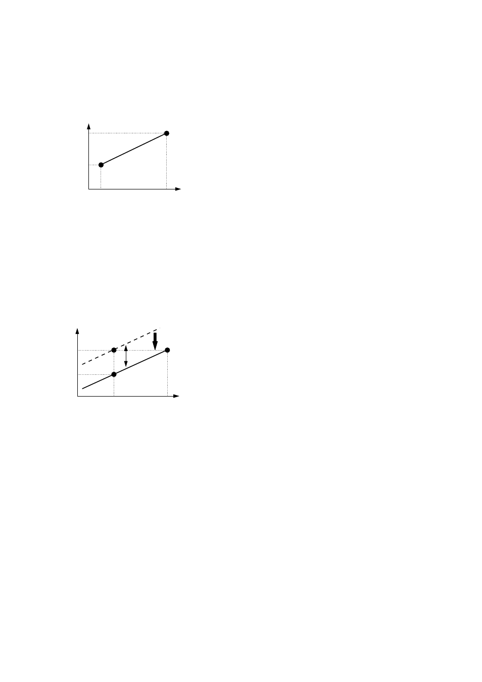
This is the function to move the line which passes above two points to the Y axis direction in parallel
(increase or decrease y intercept of the line). The parallel movement amount including a sign is defined as
the calibration offset. This function can conform the display temperature of the operation panel to the
measurement temperature of a voluntary point in the chamber at a voluntary temperature.
In Fig. 2, D
SV
is a display temperature of the
operation panel under the condition that the
temperature in the chamber is constant for a set
temperature. It is natural to say that this value is
equal to the target set temperature. D
PV
is a
measurement temperature of a voluntary point in the
chamber under this condition. The difference
between D
PV
and D
SV
including the sign is defined
as the calibration offset. Therefore offset is shown
as below.
In Fig. 2,
ΔD
CAL
becomes the negative value since the target
set temperature D
SV
is larger than the actually measured
temperature D
PV
. In order to conform the display
temperature to the actually measured temperature, let the controller to recognize that the temperature in the
chamber differs from the target set temperature by
ΔD
CAL
.
NOTE: Setting Tolerance of Calibration Offset
♦ The calibration offset can be set within ±5% of the maximum working temperature of the oven.
(Therefore, the setting tolerance of the calibration offset is ±19°C.)
♦ Initial off set value has been set to 0°C when shipping.
D
S
Sensor detection temperature
Display temperature
(Controlled temperature)
T
0
T
S
D
0
y=ax+b
Fig. 1
D
SV
D
PV
T
i
T
V
Parallel movement
△
D
CAL
Display temperature
(Controlled temperature)
Sensor detection temperature
Fig. 2
△D
CAL
=D
PV
-D
SV
Equation 1