Safety devices and error codes – Yamato Scientific DN410H Constant Temperature Ovens User Manual
Page 30
24
Safety Devices and Error Codes
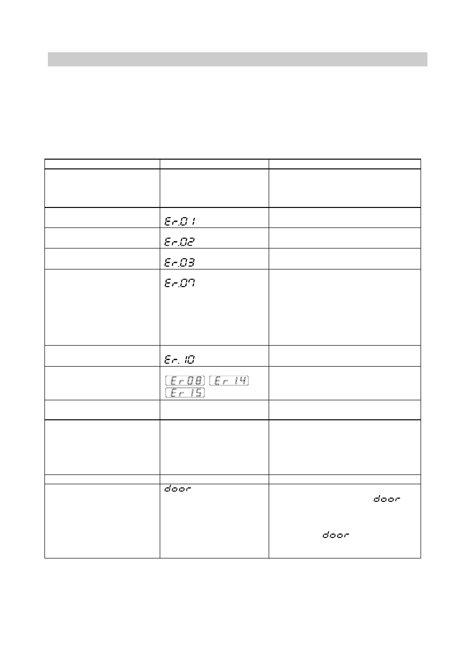
Purposes and Operations of Safety Device and Counter-measures
This instrument incorporates an automatic diagnosis function built in the controller and safety
devices independent of the controller. The purposes and operations of the safety devices and
countermeasures are shown in the Table below. When an abnormal condition occurs, an error
code is displayed in the main display. Immediate action should be taken according to the specific
counter-measures.
Safety Device
Display
Cause & Counter-measures
1. Earth leakage breaker
No Display
• Power circuit interrupted
• Erases all displays
⇒ Report to our service office and
check the cause of the problem.
2. Sensor malfunction
detector
TROUBLE lamp flashes.
flashes.
• Break in temperature sensor circuit.
⇒ Report to our service office.
3. Triac circuit detector
TROUBLE lamp flashes
flashes.
• Short circuit in triac.
⇒ Report to our service office.
4. Disconnected heater circuit
detector
TROUBLE lamp flashes
flashes.
• Heater circuit is disconnected.
⇒ Report to our service office.
5. Independent overheating
prevention
TROUBLE lamp flashes
flashes.
• Incorrect setting of the independent
overheating prevention.
⇒ Set correctly.
• Heating of sample
⇒ Reduce the amount of the sample.
• Malfunction of the independent
overheating prevention circuit.
⇒ Report to our service office.
6. Main relay malfunction
detector
TROUBLE lamp flashes
flashes.
• A malfunction of the main relay.
⇒ Report to our service office.
7.
POST function*
TROUBLE lamp flashes
,
,
flashes.
• Contact Yamato Sciectific’s
Technical Service Department.
8. Automatic overheating
preventive function
No Display
• Heating of samples
⇒ Reduce amount of samples
9. Key lock
Key lock display lamp lights up
•
This function prevents the disruption
of operation due to incorrect
operation. Leave it on during
operation. (See section in this
manual for setting and resetting
methods on page 21).
10.
Memory backup circuit
No Display
11. Door switch
flashes
• It is not the fault.
⇒ When opened the door,
will
flash on the sub display and the
heater circuit will be cut off and the
fan will stop for safety. Once closed
the door,
will go out and
the heater circuit and the fan will
resume working.
z POST (Power On Self Test) function checks the microprocessor, memory surrounding LSI, surrounding
circuit of the controller every time “POWER” key is turned ON. This is the function for checking that the
controller won’t have a fatal fault before starting the operation.