Weidmuller PRO-H Series Power Supplies User Manual
Page 6
Tel: (800) 849-9343
Fax: (804) 379-2593
www.weidmuller.com
Date:
28 September
2009
Issue: 1.0
Page
6
3.2 Thermal behavior:
The device should not be operated at higher loads than indicated on the derating graphs Fig. 4.1 and Fig. 4.2). The device does switch off at
thermal overload. After sufficent cooling the device will switch on again.
3.3 Parallel operation:
Maximum 5 devices of the same type can be connected in parallel to enable increased output power. For
n parallel connected devices the
output current can be increased to
n x Imax. Parallel connection to increase efficiency is used for the expansion of existing systems. It is
advisable to use parallel connection if the power supply does not cover the current requirement of the most powerful consumer. Otherwise the
consumers should be spread among individual devices independent of one another.
To provide a proper and reliable start-up the jumper at connector J4 has to be set (see Fig. 5.1, Fig. 5.2, Fig. 5.3 & Fig. 5.4). If the jumper is set
between pin 1 and pin 2 of connector J4 the unit is in normal mode. If the jumper is set between pin 2 and pin 3 on connector J4 the unit can be
paralleled. At delivery this jumper is set for normal operation (between pin 1 and pin 2 of connector J4).
If the output voltage is adjusted, a uniform distribution of power is guaranteed by setting all parallel operated power supplies to exactly the
same output voltage. To ensure symmetrical distribution of power, we recommend designing all cable from the power supply as busbar of the
same length and with the same conductor cross section. The system makes it advisable to install a protective circuit at the output of each
device when more than two power supplies are connected in parallel (e.g. decoupling diode or DC fuse). This prevents high reverse feed
currents in the event of a secondary device fault.
3.3.1 Redundancy operation:
Possible by use of our redundancy module CP T RM 10 or CP T RM 20. With this module and two power supplies of the PRO-H Series (CP T SNT
70W 12V 6A, CP T SNT 90W 24V 3.8A, CP T SNT 140W 12V 12A, CP T SNT 180W 24V 7.5A and CP T SNT 360W 24V 15A in combination
with CP T RM 10 or CP T SNT 600W 24V 25A in combination with CP T RM 20) a highly reliable, true redundant power system can be
configured without any additional components. This module enforces the equivalent sharing of the output current by each power supply. The
system is fully redundant and provides the output power even if one power supply has completely failed e.g. by short circuit on the output. In
the event of either, one power supply failing or being disconnected, the second unit will automatically supply the full current to the load. The
redundancy of the system is monitored and if lost, indicated by an alarm output. The inputs are hot swappable and can be loaded up to 15A
each (CP T RM 10) or up to 25A each (CP T RM 20).
3.6 Remote ON/OFF:
The standard unit provides a remote on/off function by use of pin 2 at connector J3 (see Fig. 3.1, Fig. 5.1, Fig. 5.2, Fig. 5.3 & Fig. 5.4). To
switch off the power supply a connection between Connector J3 pin 2 (-S) and Connector J2, pin 1 (–Vout) by use of a 1kΩ resistor has to be
made. At open connection between J3 pin 2 and J2 pin 1 the device is providing the adjusted output voltage.
4. Additional information for the North American Market for UL508
The PRO-H series power supplies are built-in units and must be installed in a cabinet with minimum dimensions of:
400mm (Width) x 500mm (Height) x 200mm (Depth)
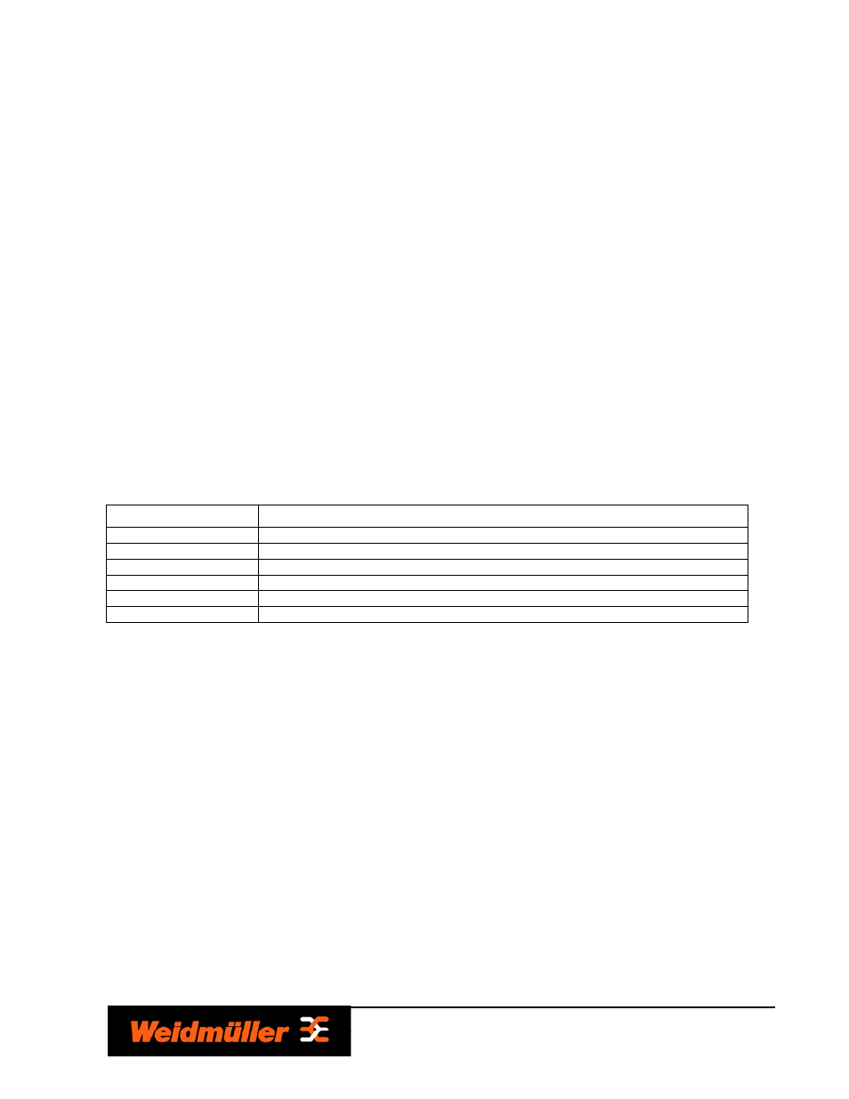
4.1 Operating Temperature Ranges and load derating:
Model
Operating Temperature Range
CP T SNT 70W 12V 6A
-25 – 40°C 100% (40 – 60°C Load derating by 0.5
W
/
°C
) (60 – 70°C Load derating by 2.0
W
/
°C
)
CP T SNT 90W 24V 3.8A
-25 – 40°C 100% (40 – 60°C Load derating by 1.5
W
/
°C
) (60 – 70°C Load derating by 2.0
W
/
°C
)
CP T SNT 140W 12V 12A
-25 – 40°C 100% (40 – 60°C Load derating by 3.0
W
/
°C
) (60 – 70°C Load derating by 4.0
W
/
°C
)
CP T SNT 180W xx
-25 – 40°C 100% (40 – 60°C Load derating by 3.0
W
/
°C
) (60 – 70°C Load derating by 4.0
W
/
°C
)
CP T SNT 360W xx
-25 – 40°C 100% (40 – 60°C Load derating by 6.0
W
/
°C
) (60 – 70°C Load derating by 8.0
W
/
°C
)
CP T SNT 600W xx
-25 – 40°C 100% (40 – 60°C Load derating by 6.0
W
/
°C
) (60 – 70°C Load derating by 16.0
W
/
°C
)