Weidmuller PRO-H Series Power Supplies User Manual
Page 4
Tel: (800) 849-9343
Fax: (804) 379-2593
www.weidmuller.com
Date:
28 September
2009
Issue: 1.0
Page
4
2.2 Connecting cable
Only qualified personnel may carry out the installation.
The devices are equipped with PCB plug connectors (CP T SNT 70W 12V
6A, CP T SNT 90W xx, CP T SNT 140W 12V 12A, CP T SNT 180W xx and CP T SNT 360W xx) or PCB terminals (CP T SNT 600W xx). This
reliable and easy-to-assemble connection method enables a fast connection of devices and a visible isolation of the electrical connection if
necessary.
2.2.1 Input
(Fig. 5.1, Fig 5.2, Fig 5.3 and Fig. 5.4 Connector J1):
The 100-240VAC connection is made by using the L, N and connections and has to be carried out in accordance with the local regulations.
Sufficiently dimensioned input wiring has to be ensured (see 2.2.1.1). A protective device (fuse, MCB, etc; see 2.2.1.2) and an easily
accessible isolating device for disconnecting the power supply from mains must be provided. The protective earth conductor has to be
connected.
If flexible wires are used the wires have to be terminated. (e.g. by using ferrules)
Note: This unit contains an automatic input voltage selection switch. Do not change the input voltage from 110/115Vac to
230/240Vac without disconnecting the input supply line first.
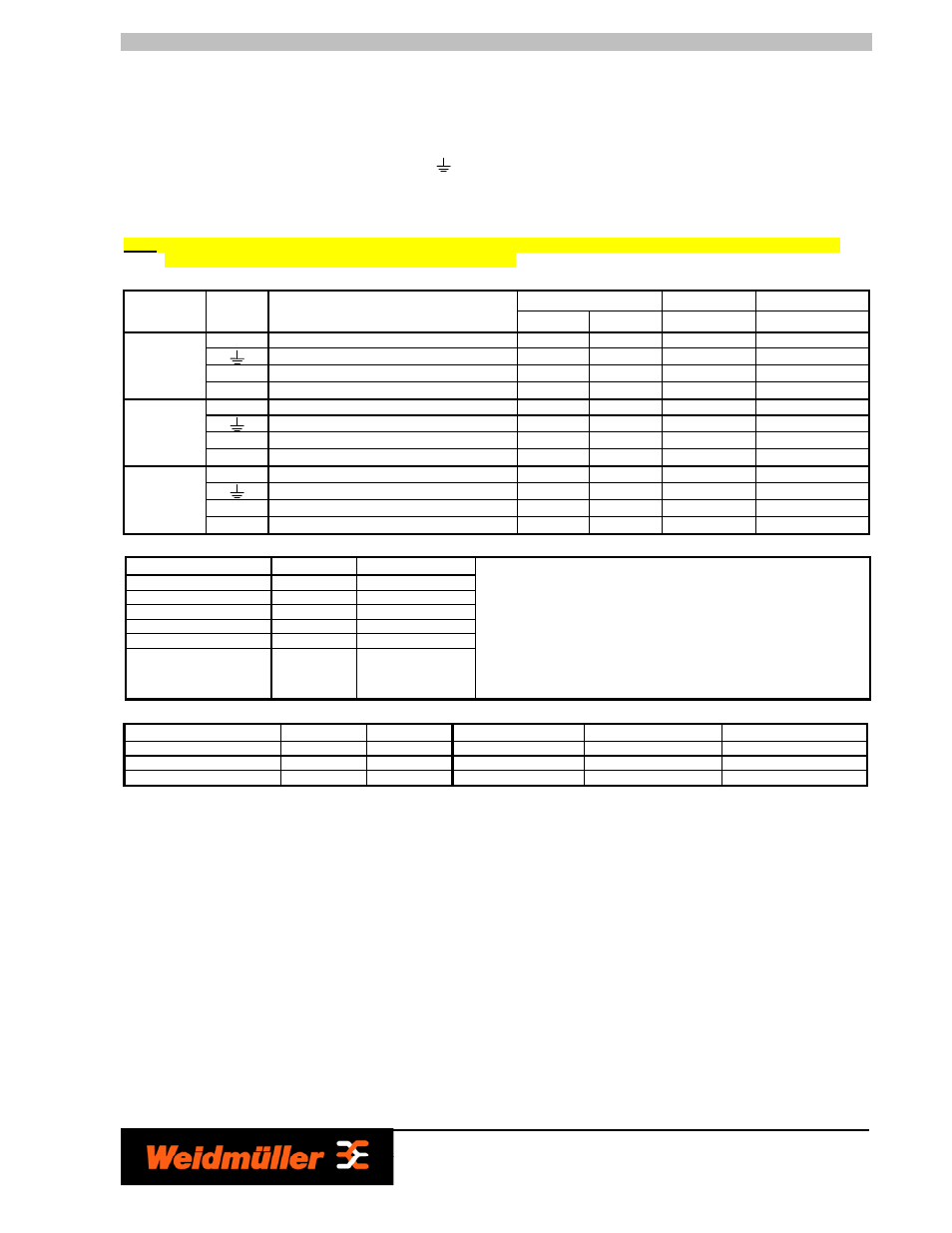
2.2.1.1 Connections and terminal assignment
Solid or stranded wires
Torque
Stripping length
Unit
Terminals Function
[mm
2
]
[AWG]
[Nm]
[mm]
L1 & N
Input Voltage (85 – 264VAC or 115/240VAC) 0.5 … 2.5
24 … 12
0.5 – 0.6
7.0
Protective Earth Conductor
0.5 … 2.5
24 … 12
0.5 – 0.6
7.0
+ & -
Output Voltage (24VDC)
0.5 … 2.5
24 … 12
0.5 – 0.6
7.0
CP T SNT (90W
24V 3.8A, 180W
24V 7.5A,
180W 48V 4A)
Signal
DC-OK, active output and relay outputs
0.2 … 2.5
32 … 12
0.5 – 0.6
7.0
L1 & N
Input Voltage (85 – 264VAC or 115/240VAC) 0.5 … 2.5
24 … 12
0.5 – 0.6
7.0
Protective Earth Conductor
0.5 … 2.5
24 … 12
0.5 – 0.6
7.0
+ & -
Output Voltage (12VDC and 24VDC)
1.0 … 2.5
18 … 12
0.5 – 0.6
7.0
CP T SNT (70W
12V 6A, 140W
12V 12A, 360W
24V 15A, 360W
48V 7.5A)
Signal
DC-OK, active output and relay outputs
0.2 … 2.5
32 … 12
0.5 – 0.6
7.0
L1 & N
Input Voltage (115 / 230VAC)
1.0 … 4.0
18 … 10
0.5 – 0.6
7.0
Protective Earth Conductor
1.0 … 4.0
18 … 10
0.5 – 0.6
7.0
+ & -
Output Voltage (24VDC)
2.0 … 4.0
12 … 10
0.5 – 0.6
8.0
CP T SNT
(600W 24V 25A,
600W 48V
12.5A)
Signal
DC-OK, active output and relay outputs
0.2 … 2.5
32 … 12
0.5 – 0.6
7.0
2.2.1.2 Internal Fuse
2.2.1.3 Recommended external Fuses (MCB)
Model
Ratings
Characteristic
Model
Ratings
Characteristic
CP T SNT 70W 12V 6A
6 - 16A / 250V
B
CP T SNT 180W xx
6 - 16A / 250V
B
CP T SNT 90W 24V 3.8A
6 - 16A / 250V
B
CP T SNT 360W xx
10 - 16A / 250V
B
CP T SNT 140W 12V 12A
6 - 16A / 250V
B
CP T SNT 600W xx
16 - 25A / 250V
B
2.2.2 Output
(Fig. 5.1, Fig 5.2, Fig 5.3 and Fig. 5.4 Connector J2):
The 12VDC, 24VDC or 48VDC connection is made using the “+” and “-“ connections. All output terminals should be connected to the load.
Make sure that all output lines are dimensioned according to the maximum output current (see 2.2.1.1) or are separately protected! The wires
on the secondary side should have large cross sections in order to keep the voltage drops on these lines as low as possible.
To achieve a reliable and shockproof connection strip the connecting ends according 2.2.1.1. If flexible wires are used the wires have to be
terminated. (e.g. by using ferrules)
At the time of delivery, the output voltage is either 12VDC, 24VDC or 48VDC. The output voltage can be set (using an insulated screwdriver)
from 12 to 14VDC, 24 to 28VDC or 48 to 56VDC on the potentiometer (see Fig. 5.1, Fig. 5.2, Fig. 5.3 and Fig. 5.4).
The device is electronically protected against overload and short circuit. In the event of malfunction, the output voltage is limited to 20VDC for
12VDC units, 35VDC for 24VDC units or 60VDC for 48VDC units.
2.2.3 Signalling
(Fig. 5.1, Fig 5.2, Fig 5.3 and Fig. 5.4 Connector J2):
The two DC-OK outputs are for enabling monitoring of the functions of the power supply. A floating signal contact (see Fig. 5.1, Fig 5.2, Fig 5.3
and Fig. 5.4 Connector J2, pin 6 & pin 7) and an active DC-OK signal (see Fig. 5.1, Fig 5.2, Fig 5.3 and Fig. 5.4 Connector J2, pin 5) are
available. The DC-OK LED also enables a visual evaluation of the function of the power supply directly on site.
2.2.3.1 Floating contacts
(Fig. 5.1, Fig 5.2, Fig 5.3 and Fig. 5.4):
The floating signal contacts opens and signals a drop in the output voltage below: 12VDC units between 9 and 11VDC; 24VDC units
between 18 and 22VDC; 48VDC units between 36 and 44VDC. Relay contacts are available at CP T SNT 70W 12V 6A and CP T SNT 90W
24V 3.8A: Connector J2, pin 4 and pin 5 / CP T SNT 140W 12V 12A, CP T SNT 180W xx and CP T SNT 360W xx: Connector J2, pin 6 and pin
7 / CP T SNT 600W xx: Connector J5, pin 1 and pin 2). Signals and ohmic loads up to 30VDC and currents of up to 1A can be connected on
the 12VDC and 24 VDC units or 48VDC and current up to 0.5A for 48VDC units. For heavily inductive loads such as relay, a suitable protection
circuit (e.g. damping diode) is necessary.
Model
Ratings
Marking
CP T SNT 70W 12V 6A
4.0 AH/250V
F1 4.0 AH/250V
CP T SNT 90W 24V 3.8A
4.0 AH/250V
F1 4.0 AH/250V
CP T SNT 140W 12V 12A 4.0 AH/250V
F1 4.0 AH/250V
CP T SNT 180W xx
4.0 AH/250V
F1 4.0 AH/250V
CP T SNT 360W xx
6.3 AH/250V
F1 6.3 AH/250V
CP T SNT 600W xx
12.0 AH/250V
F1 12.0 AH/250V
CAUTION:
For continued protection against risk of fire
replace with same type and rating of fuse! This
fuse should be changed only by authorised and
trained personnel because it is soldered on the
board
If the internal fuse is triggered, there is most
probably an internal malfunction which must be
inspected in the factory. Due to that return this
device to your local distributor.