Weidmuller PRO-H Series Power Supplies User Manual
Page 5
Tel: (800) 849-9343
Fax: (804) 379-2593
www.weidmuller.com
Date:
28 September
2009
Issue: 1.0
Page
5
2.2.3.2 Active signal output
(Fig. 5.1, Fig 5.2, Fig 5.3 and Fig. 5.4):
11VDC ±1VDC (12VDC units), 22VDC ±2VDC (24VDC units) or 44VDC ±4VDC (48VDC units) is applied between the “DC-OK” (CP T SNT
70W 12V 6A and CP T SNT 90W 24V 3.8A: Connector J2, pin 3 / CP T SNT 140W 12V 12A, CP T SNT 180W xx and CP T SNT 360W xx:
Connector J2, pin 5 / CP T SNT 600W xx: Connector J5, pin 3) and “-“ (Connector J2, pin 1) and can carry up to 40mA max. (12VDC units) or
10mA max (CP T SNT 90W 24V 3.8A(N) or 20mA max. (other 24VDC units) or 15mA max (48VDC units). This signal output is referenced to –
Vout (GND) and signals when the output voltage drops below: 12VDC units between 9 and 11VDC; 24VDC units between 18 and
22VDC; 48VDC units between 36 and 44VDC by switching from high to low.
The DC-OK signal is decoupled from the power output. It is thus not possible for parallel-switched devices to provide external supply. The DC-
OK signal can be directly connected to a logic input for evaluation.
2.2.3.3 Signal loop:
The two above-mentioned signals can be easily combined.
Example: Monitoring of two devices.
Use the active signal output of device 1 and loop in the floating signal output of device 2. In the event of malfunctioning a common alarm is
available. Up to 5 units can be looped in. This signal combination saves wiring costs and logic inputs.
2.2.3.4 DC-OK LED:
The DC-OK LED is a two colour LED which indicates the status of the output and enables visual evaluation of the function locally in the control
cabinet. DC-OK LED green – normal operation. DC-OK LED red – output failure if input mains is still present.
3. Function
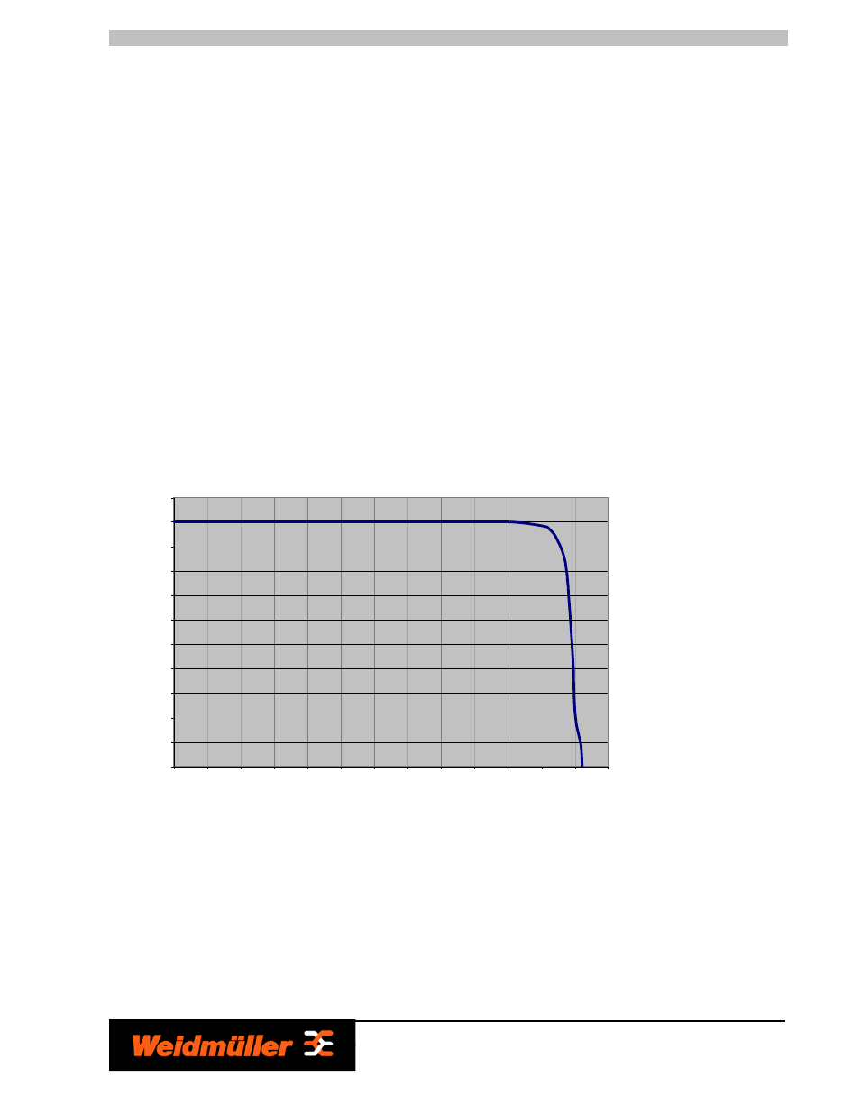
3.1 Output characteristic curve:
In the case that the ambient temperatures is not higher than +40°C, the device can continuousely supply Iout max (see datasheet). In the
event of a higher load, the operating point follows the U/I charateristic curve by use of overcurrent protection. The output current is limited at
Iout max. by use of a constant current characteristic with automatic restart if the short circuit or over load condition has been removed.
The U/I characteristic curve ensures that heavily capacitive loads can be fed without problems.
Current Limitation Curve of TSP Power Supplies
0.00
10.00
20.00
30.00
40.00
50.00
60.00
70.00
80.00
90.00
100.00
110.00
0.00
10.00
20.00
30.00
40.00
50.00
60.00
70.00
80.00
90.00
100.00
110.00
120.00
130.00
I
out
[%]
V
ou
t
[%]
Current Limitation Curve