Pi33xx-2x i, C digital interface guide, Addressing & register mapping – Vicor PI33XX-2X I2C Digital Interface Guide User Manual
Page 3
vicorpower.com Rev 1.0
Cool-Power
®
800 735.6200 11/2012 Page 3 of 22
PI33XX-2X I
2
C Digital Interface Guide
Addressing & Register Mapping
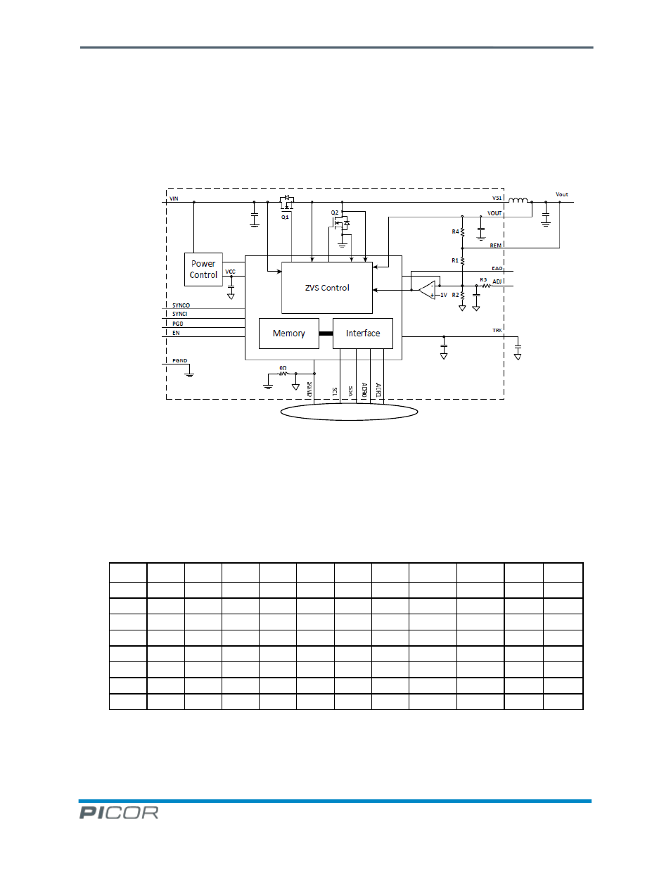
Figure 2 shows the PI33XX-2X I
2
C hardware interface. The PI33XX-2X supports floating addressing so that two
address lines allows for up to 8 programmable addresses. The address is 7 bit with the read/write bit not included.
Table 1 shows the address range that can be achieved using all possible combinations of ADR0 and ADR1. Bits A[6]-
A[3] are fixed internally and may not be changed.
Figure 2 - PI33XX-2X Block Diagram Showing I
2
C Hardware Interface
The least significant 3 bits; A[2]-A[0], will assume the values in the table based on the decoding of ADR1 and ADR0.
A zero or one indicates the logic strength of the bit and “NC” indicates that the pin is floating or not connected.
The HEX column indicates the final address in hexadecimal, while the DEC column is the decimal address value.
A[6]
A[5]
A[4]
A[3]
A[2]
A[1]
A[0]
R/W
ADR1
ADR0
HEX
DEC
1
0
0
1
0
0
0
X
0
0
48
72
1
0
0
1
0
0
1
X
0
NC
49
73
1
0
0
1
0
1
0
X
0
1
4A
74
1
0
0
1
0
1
1
X
NC
0
4B
75
1
0
0
1
1
0
0
X
NC
NC
4C
76
1
0
0
1
1
0
1
X
NC
1
4D
77
1
0
0
1
1
1
0
X
1
0
4E
78
1
0
0
1
1
1
1
X
1
1 + NC
4F
79
Table 1 - Addressing Options (logic 1 => 1V)
I
2
C Hardware Interface Signals