Pi33xx-2x i, C digital interface guide, Configuration example - sync delay – Vicor PI33XX-2X I2C Digital Interface Guide User Manual
Page 17
vicorpower.com Rev 1.0
Cool-Power
®
800 735.6200 11/2012 Page 17 of 22
PI33XX-2X I
2
C Digital Interface Guide
Configuration Example - Sync Delay
Type “0001” into the SYNC dialog box. Left click on the “BURN” button.
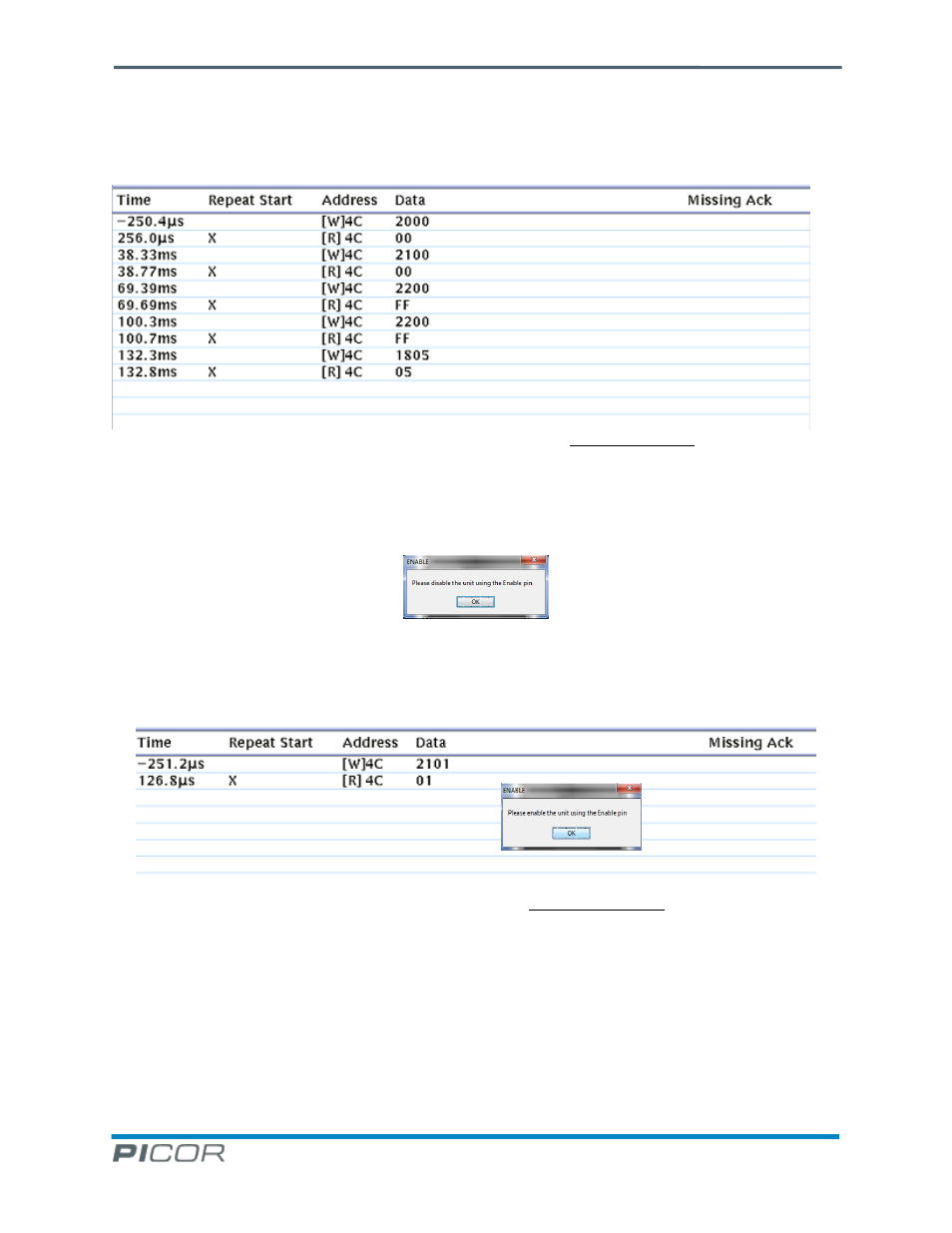
Figure 20 - SYNC “0001” Burn Phase 1 While Unit Enabled or Disabled
The first four writes and reads ensure that the three User registers are cleared. Then the test mode register is
selected at address 18h and the test mode 05h is entered. Next, the user is prompted to disable the unit using the
enable pin. The target can be enabled or disabled prior to being prompted to disable. See Figures 20 and 21.
Figure 21
When the user disables the target, another prompt will provide notification to enable the target again as shown in
Figure 22. When the unit is enabled, the output voltage will remain low as if the PI33XX-2X was still disabled. This
is normal. The Picor Buck GUI will next write “01h” into the SYN[3:0] register.
Figure 22 - SYNC “0001” Burn Phase 2 Unit Must be Enabled
The next step prompts the user to disable the target again. After clicking “OK”, Picor Buck GUI will reset from test
mode 5 and then clear the other user registers as shown in Figure 23. Picor Buck GUI will display a dialog box to
inform the user of the successful burn completion. When the user enables the PI33XX-2X, it should power up
normally and the burned in changes shall take effect.