Technical description – Vicor DC MegaPAC DC-DC Switcher User Manual
Page 5
Rev. 3/04
Vicor 800-735-6200 Mission Power Solutions (760) 631-6846 (phone) or (760) 631-6972 (fax)
Pg. 5
DC MegaPAC Operator’s Manual
Technical Description
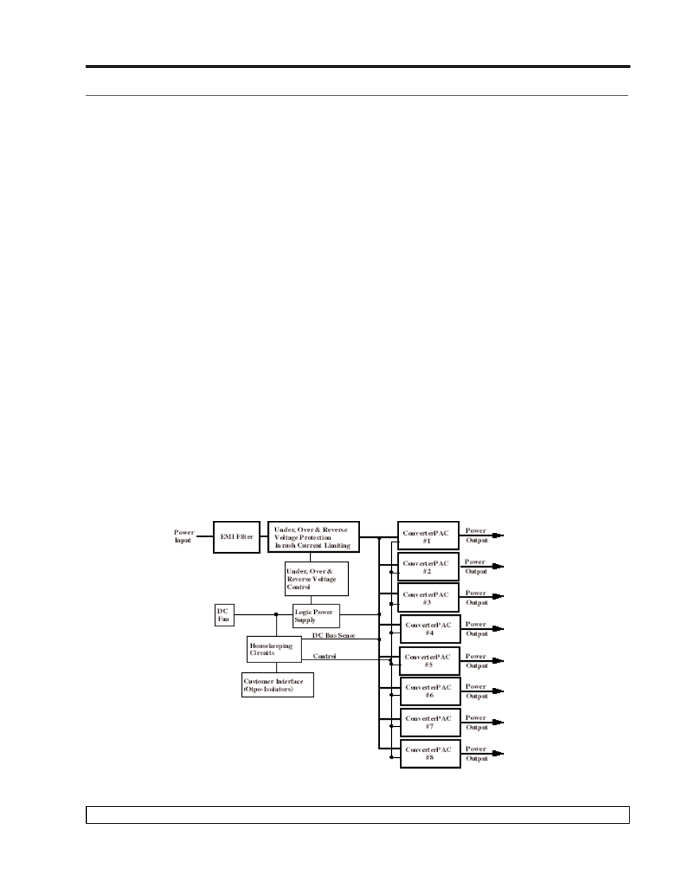
The DC MegaPAC chassis consists of an EMI filter, cooling fan, customer interface and associated housekeeping circuits.
Input DC voltage (+VIN, -VIN, and GND) is applied to the input connectors. The input current is passed through an EMI
filter designed to meet conducted British Telecom specifications. At start-up, inrush current is limited by a thermistor. The
thermistor is shunted out shortly after initial power-up by a relay driven by a DC bus voltage sense circuit. The DC voltage
is then fed to the backplane. The backplane supplies power to a variety of ConverterPAC assemblies that provide the
desired low voltage, regulated outputs.
Voltage conversion in the output assemblies is achieved by Vicor's family of Zero-Current-Switching (ZCS) DC-DC con-
verters. These are forward converters in which the main switching element switches at zero current. This patented topology
has a number of unique attributes: low switching losses; high frequency operation resulting in reduced size for magnetics
and capacitors; excellent line and load regulation; wide adjustment range for output; low EMI/RFI emission and high effi-
ciencies.
At initial power-up, the DC MegaPAC outputs are disabled to limit the inrush current and to allow the DC bus potential to
charge to the operating level. A low-power flyback converter operating with PWM current-mode control converts the DC
bus into regulated low voltage to power the internal housekeeping circuits and DC cooling fan. When operating on 48 Vdc,
the internal housekeeping Vcc comes up within 3s after the application of input power. Once the input range is within speci-
fication, the VIN OK signal asserts to a TTL "1" indicating the input power is OK, and allows the power outputs to be
enabled. The power outputs will be in regulation 500 ms after the Vin OK signal asserts to a TTL "1." An auxiliary Vcc out-
put of 5 Vdc sourcing up to 0.3A is provided for peripheral use.
An output Enable/Disable function is provided by using an optocoupler to control the Gate In pins of the ConverterPAC
assemblies. If the Enable/Disable control pin is pulled low, the optocoupler turns on, pulling the Gate In pin low and dis-
abling the ConverterPAC output. The nominal delay associated for an output to come up when measured from release of the
Enable/Disable pin is 5-10 ms. The General Shutdown function controls all outputs simultaneously and works in a similar
manner. If driven from an electromechanical switch or relay, a capacitor should be connected to eliminate the effects of
switch bounce.
There is no ride-through (holdup) time available with the DC MegaPAC.
Figure 1. DC MegaPAC Architecture