Vicor DC MegaPAC DC-DC Switcher User Manual
Page 11
Rev. 3/04
Vicor 800-735-6200 Mission Power Solutions (760) 631-6846 (phone) or (760) 631-6972 (fax)
Pg. 11
DC MegaPAC Operator’s Manual
Signal Ground (J3-1)
Signal Ground on J3-1 is an isolated secondary ground reference for J3 status signals. It is used to provide a refer-
ence point for the Power Good circuitry and is not the same as Earth Ground on input power connector J9.
Vcc In (J3-4)
The Vcc In on J3-4 is an input that requires +5V either from the J10 Auxiliary Vcc, or from another source. Input
current to this pin is limited by an internal resistor to 3 mA. If the J10 Auxiliary Vcc is connected to Vcc In on J3-
4, then at least one J10 Signal Ground must be connected to Signal Ground on J3-1.
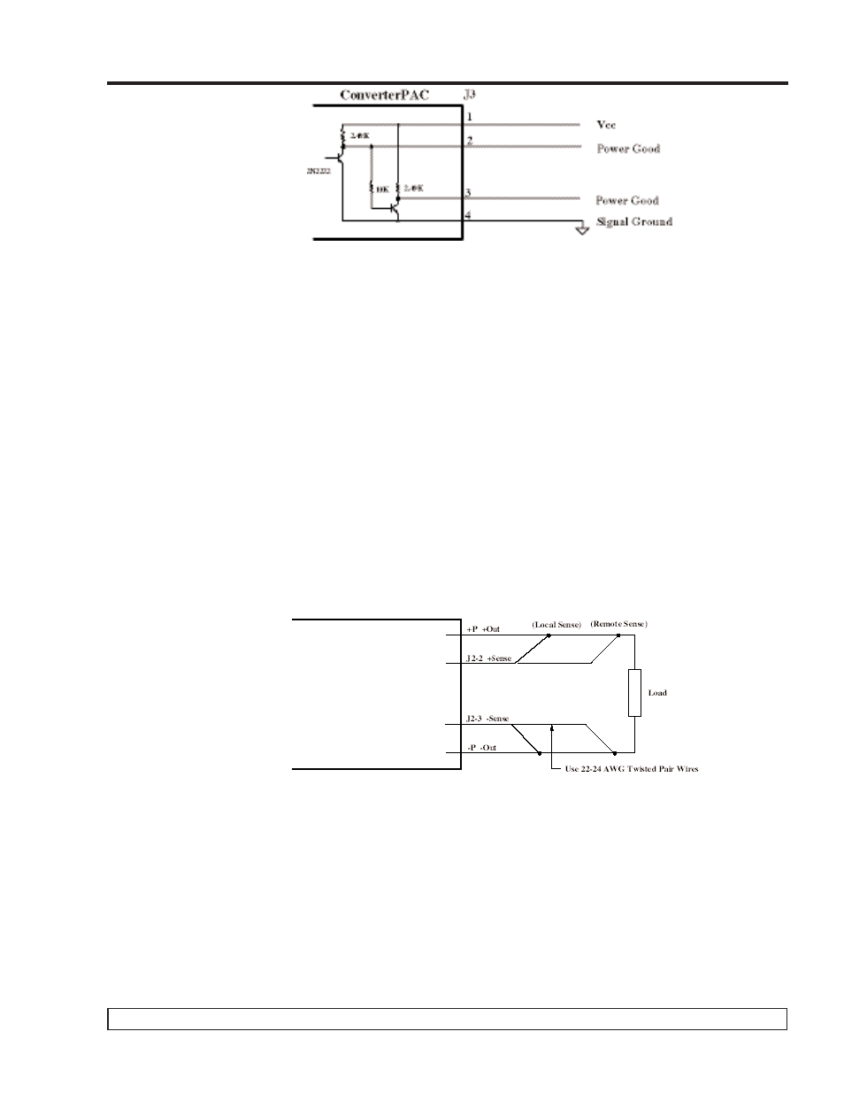
+Sense/–Sense (J2-2 and J2-3)
The +Sense on J2-2 should be connected to the +Power Out, and the –Sense on J2-3 to the –Power Out terminal.
Do not reverse or leave the Sense pins open. Sense pins can be terminated locally at the output of the power sup-
ply, in which case the power supply will provide regulation at the output terminals. The voltage appearing at the
load may drop slightly due to voltage drop in the power cables. If it is necessary to compensate for voltage drop
along the output power cables, this termination should be made close to the output load. Compensation of up to
0.5V (0.25V per lead) can be obtained. Use twisted pair 22-24 AWG wire for this purpose.
For DualPACs, the +Sense pins are available on connectors designated as J2A-2 and J2B-2 for outputs A and B,
respectively. –Sense pins are on J2A-3 and J2B-3, respectively. These pins are also duplicated on the power con-
nectors J1A and J1B.
External Trim (J2-1)
Output voltage can be trimmed using an optional factory-installed Trim potentiometer or with the Trim pin (see
Figure 13). The Trim potentiometer is located on the ConverterPAC. If the Trim potentiometer has not been
ordered, the Trim pin must be used. When using the Trim pin, the Trim limits are determined by the DC/DC con-
verter used on the ConverterPAC. Maximum Trim ranges are 10% above the nominal converter voltage and 50%
below the nominal converter voltage.
The Trim pin on J2 can be used to control the output voltage. It is referenced to the -Sense pin on J2 and can be
controlled by either a resistor network or an external voltage source. To increase an output voltage above its nomi-
nal, it is necessary to increase the voltage at the Trim pin above the internal reference voltage (Vref). The reverse
is true to decrease an output voltage.
Figure 12. Sense Leads
Figure 11. Power Good and Vcc