S&S Cycle Super E and G Series Shorty Performance Carburetors for 1936-84 Harley-Davidson Big Twins and 1957-85 Ironhead Sportster Models User Manual
Page 15
15
•
If bike is used exclusively on drag strip where engine
temperatures vary, slightly richer jets may be necessary to
obtain best performance. Larger jets and richer mixtures
will enable one to run colder engine, which is sometimes
desirable. This is best determined by experimentation.
•
Cams and exhaust systems can make some engines
difficult to carburet. S&S has found that certain cams and
exhaust systems cause poor performance at a specific rpm,
and attempts to correct problem with carb tuning usually
degrade carburetion at other rpm ranges. A combination
of cam overlap, reversion, and back pressure, or even lack
of back pressure, can cause mixture dilution at certain rpm.
This will result in loss of power, engine roughness, or
misfiring.
•
Drag pipes –S&S does not recommend the use of straight
drag pipes for street applications. They typically display a
characteristic dip in midrange performance, and make
tuning more difficult.
•
Mufflered exhaust systems - A good, economical street
exhaust system consists of stock header pipes with cross-
over tube and low restriction mufflers such as S&S® slip-on
mufflers. This system typically produces 10 horsepower
more than drag pipes in midrange, where vast majority of
normal riding occurs.
•
For any all-out racing application, which includes use of air
cleaner without element or use of air horn, bowl vent screw
(See Picture34, page XX), should be removed to insure
atmospheric air pressure exists in bowl. If high or low bowl
pressure relative to atmospheric pressure develops, engine
may run erratically.
F-
Picture 28
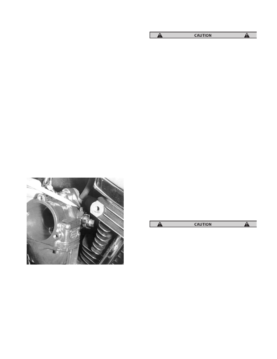
F- Adjusting Accelerator Pump - Function of accelerator
pump is to improve throttle response when rapidly
opening throttle at low rpm and to aid cold starts. Pump
travel screw regulates volume of fuel delivered by
accelerator pump. See Picture 28 During assembly, S&S
sets screw for maximum volume to aid during initial
start-up after installation. Turning screw clockwise
decreases delivered pump volume. Turning screw
counterclockwise increases delivered volume.
1- Warm engine to operating temperature.
2- Turn pump travel adjusting screw clockwise until
screw contacts pump actuator arm. This limits
actuator arm travel and shuts off pump.
Closing adjusting screw with excessive force may cause
irreversible damage to screw threads in carburetor body.
3- Perform intermediate and high speed jetting tests to
determine proper jetting.
4- With engine warm and at idle, blip throttle and note
throttle response.
5- Turn pump travel screw counter clockwise about 1⁄4
turn at a time and recheck throttle response until
engine no longer hesitates. This is usually about two
turns out.
6- Road test motorcycle noting throttle response at idle
and at levels in 500 rpm increments from idle to 3000-
3500 rpm.
7- Set pump travel screw at point where best throttle
response is noted with minimum pump travel.
Minimum pump travel is recommended to conserve
fuel, prevent spark plug fouling, and curtail black
smoke from pipes when “blipping” throttle. Black
smoke from pipes is usually an indication of a rich
condition or excessive accelerator pump travel.
NOTE: Final accelerator pump adjustment should be confirmed by
riding motorcycle and noting throttle response with motorcycle
underway. Because of displacement, compression ratio, cam timing,
exhaust design and other, related factors, many engines will stumble
or bog if throttle is abruptly cranked fully open with engine at idle. If
correct carburetor (E or G) is installed and engine properly tuned and
equipped with appropriate exhaust and cam, stumble should
disappear under normal riding conditions.
GENERAL INFORMATION NOTES:
•
Carburetor body has six drilled passages that are
permanently sealed with drive plugs.
Removal of these plugs may cause irreversible damage to
carburetor.
•
To insure proper seal so needle completely shuts off fuel
supply entering bowl, float hinge, needle lift and needle
must work freely and not bind. Float must not contact bowl
gasket. If problem is suspected, remove bowl and check
float movement. If obvious misalignment, binding or
sticking occurs, remove, straighten and reinstall to obtain
free movement. Reset float level and double check for free
movement. To check, remove bowl (not accelerator pump
cap) and raise float until needle is in closed position and
spring in top of needle is compressed. Top of float opposite
the needle and seat assembly should be 1⁄8" to 3⁄16" below
bowl gasket surface. Float must not contact bowl gasket.
See
cut
away
bowl
in
Picture
29.