Caution – RKI Instruments SD-705EC User Manual
Page 12
PT2E-1140
(2) Insert a packing gland(lower) →washer→packing→packing grand(upper) in this order
onto the cable.
Lead the cable into the detector terminal box and attach a stick-type crimp
terminal plate to the end of cable.
Cable finish O.D.
Packing inside
diameter(㎜)
Washer inside
diameter(㎜)
φ11 ∼ 12
φ12
φ13
If cable finish O.D. does not meet with above packing gland, please contact with us.
(3) Loosen the hexagonal socket headed screws (6 points) of the detector and remove
the lid, and the power terminal plate(3 points) and relay output terminal plate(6
points) appears. The power terminal plate(3P) has “+(DC24V)”, “-(DC24V)” and
“Sig” marks from left to right. The “-(DC24V)” terminal is a common terminal (-)
for the DC24V input and Sig output (DC4∼20mA). Therefore, both the +(DC24V)
and -(DC24V) terminals are for DC24V input and both the Sig and -(DC24V) are
for DC4∼20mA output.
+ −
SIG
DC24V input
4∼20mA output
The relay output terminal plate (6P) has “First alarm relay output terminal (2P)”,
“Second alarm relay output terminal (2P)” and trouble alarm relay terminal (2P).
1
2
3
4
5
6
Relay output
for 1
st
alarm
Relay output
for 2
nd
alarm
Relay output for
trouble alarm(option)
Be care not to damage the inner electronics circuit when making
wiring construction.
CAUTION
!
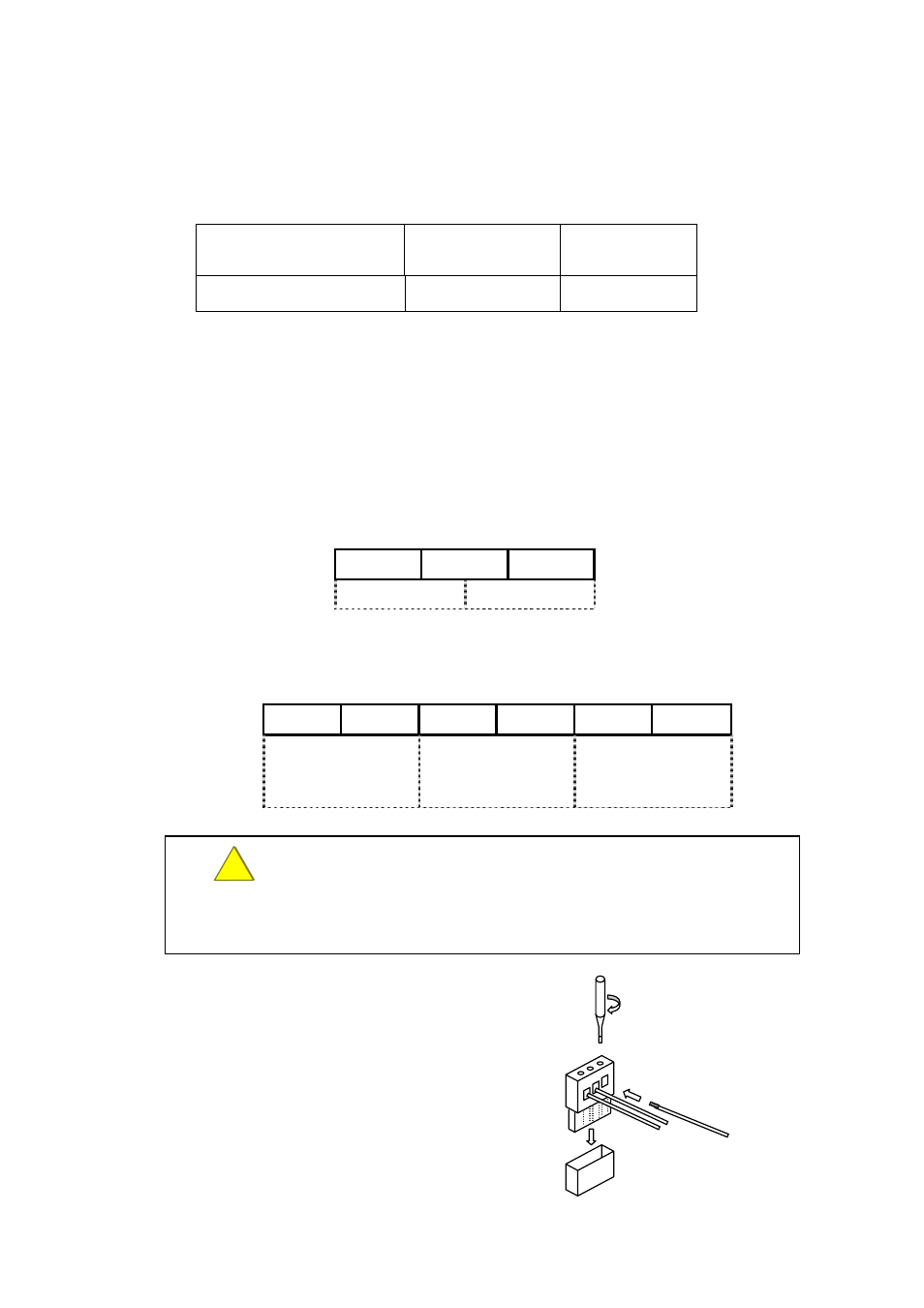
②
③
①
<
①Make the cable end naked.
(For length, refer to following
“Length of naked wires.”
② Insert the cable into plug of
terminal and tighten it by minus
screw driver.
③After completion for connection
of all cables, connect the plug
onto the base of PCB.
11