Ds dk dn dz vk pf – Retsch PT 100 User Manual
Page 26
Operating the machine
26
Fig. 7: Inserting the PT100 connection cable
Pos : 7. 29 /00005 Ü berschrif ten/ 1. 1 Ü bersc hrift en/ 1. 1 Übersc hrift en BD A/ 11 G erät und Z ut eilgerät gleic hzeitig s tart en @ 3 \ mod_1302780258781_9. doc @ 25097 @ 2 @ 1
5.12 Starting device and vibratory device simultaneously
Pos : 7. 30 /00010 Bedi enungsanleit ung en Kapitels ammlungen/ PT100 (2011)/ 0015 PT 100 Bedienung/ 1550 PT100 / PT 200 Modul G erät un d Z ut eilgerät st art en @ 3\ mod_1302779710476_9. doc @ 25018 @ @ 1
• Put sample vessels onto all sample outlets on the device.
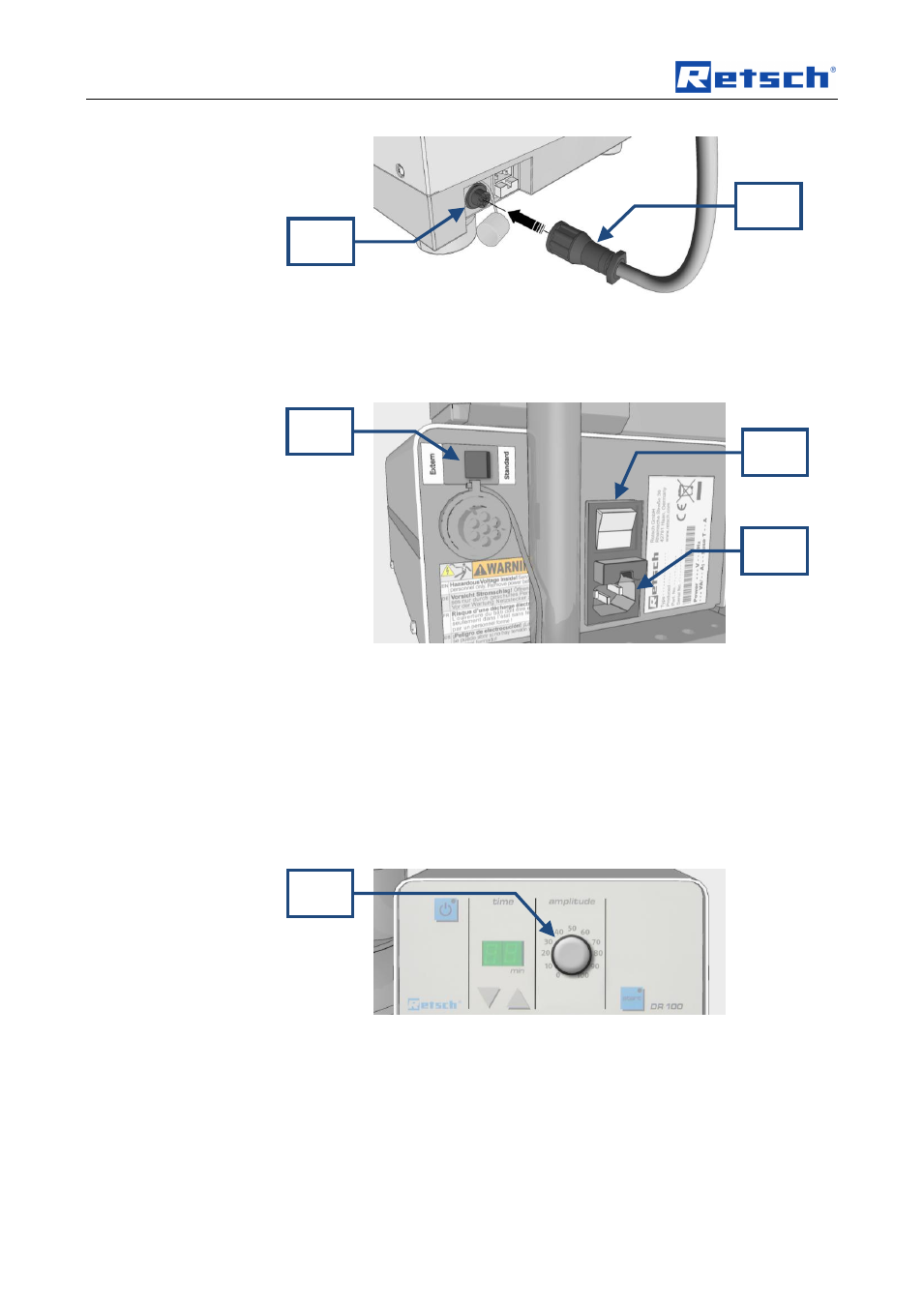
Fig. 4: Rear view of the DR100
NOTE
PT 100 and DR100 must be suitable for the same electrical mains supply, (see
type plate).
Failure to comply with the ratings on the type plate on the PT 100 and DR100 can
cause damage to electronic and mechanical components.
•
Connect the DR100 to the mains power supply using the C13 panel-
mounted male connector (inlet) (DZ).
•
Set the switch (DS) on the back of the DR100
to “Standard”.
Fig. 5: Setting the DR100 feeding speed
•
Set the feeding speed regulator (DK) on the DR100 to the required position
(depending on the material to be divided).
• Fill the DR100 feed hopper.
• Adjust the slot width between the feed hopper outlet and the push-fit chute base
(feed level).
DS
DK
DN
DZ
VK
PF