Transport, scope of delivery, installation, 9 installation of the machine – Retsch SM 200 User Manual
Page 14
Transport, scope of delivery, installation
14
•
Push the handle of the door latch (F) backwards.
•
Open the grinding chamber door (T).
•
Pull the plunger (B) into the upper latching position.
•
Place the feed hopper (R) on the device. (see diagram)
CAUTION
Until the feed hopper (R) is secured by two socket-head screws, there is a risk of it
falling out of the device.
•
Release the detent pin bolt (D) on the plunger (B).
•
Push the plunger downwards.
•
Screw the two provided socket-head screws (S) through the hinge on the
feed hopper into the enclosure.
•
At first, tighten the screws only slightly.
•
Close the grinding chamber door.
•
Pull the handle on the door latch (F) forwards until the mini detent pin (E)
engages.
•
Adjust the feed hopper until the plunger can be moved upwards and
downwards easily without jamming.
•
Tighten the two socket-head screws securely. (10 Nm)
•
Check again if the plunger moves upwards and downwards easily without
jamming.
•
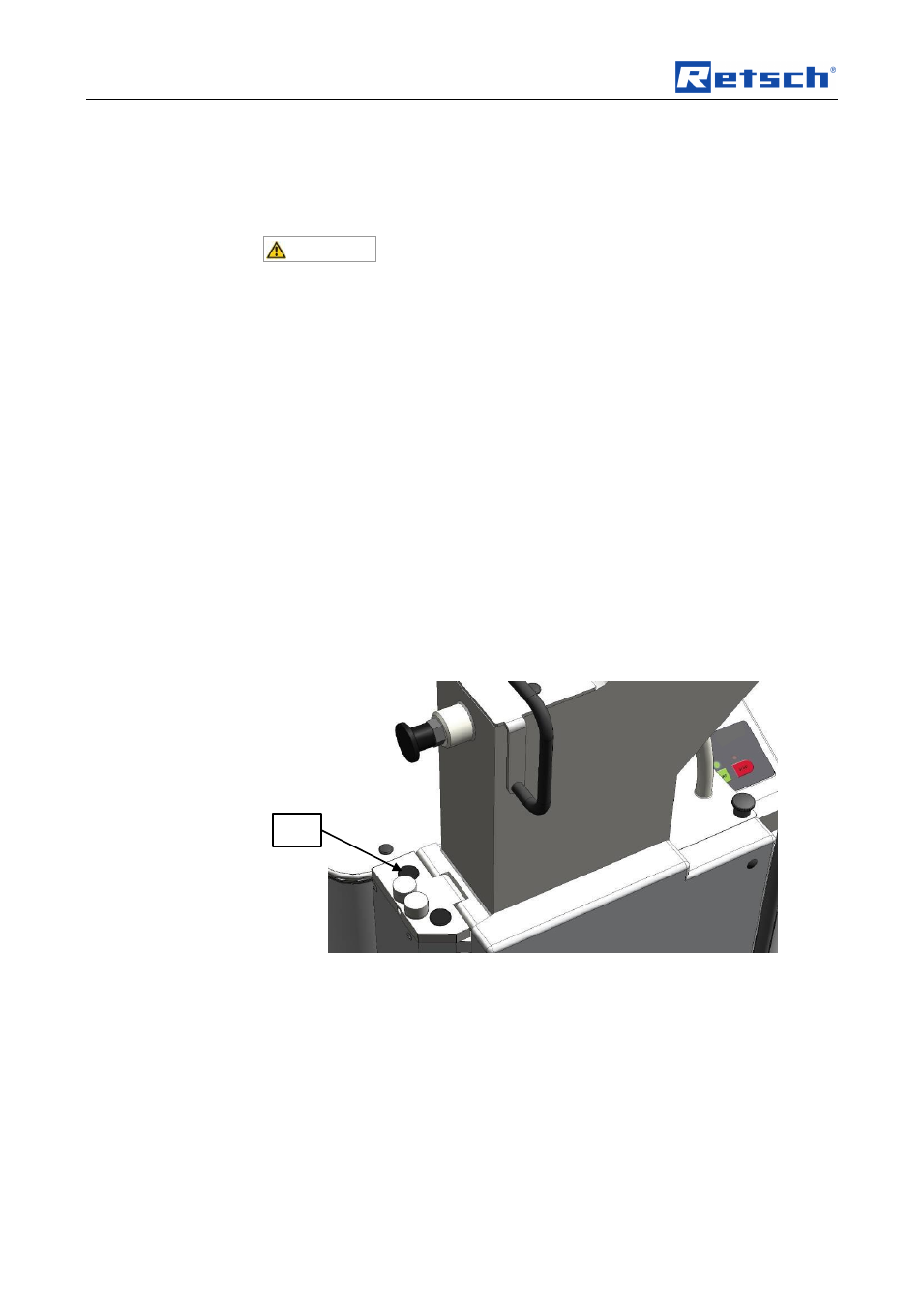
Put the two protective caps (SK) onto the screws (S).
Fig. 5: Putting on the protective caps
NOTE
When new, the grinding chamber door and the handle on the door latch are
somewhat difficult to move.
Pos : 5. 27 /00005 Ü berschrif ten/ 1. 1 Ü bersc hrift en/ 1. 1 Übersc hrift en BD A/ 11 Aufs tell en des Ger ät es @ 0\ mod_1226498849756_9.doc @ 3464 @ 2 @ 1
3.9 Installation of the machine
Pos : 5. 28 /00003 St andard Kapit el/ General M odul Aufst ellungshöhe @ 0\ mod_1228918538349_9.doc @ 4724 @ @ 1
Installation height: maximum 2000 m above sea level
Pos : 5. 29 /00004 Warnhinweis e/H 0004 HIN WEIS Boden Aufst ellen Vibr ationen Boden @ 0 \ mod_1228918882236_9. doc @ 4774 @ @ 1
S