Float spring removal or installation – MacDon 872 Combine Adapter User Manual
Page 69
69
FLOAT SPRING REMOVAL or INSTALLATION
The adapter is equipped with 8 float (leaf) springs per
side. There are two situations where it may be necessary
to change the number of leaf springs per side:
A. For the 21’ 972 Header, 8 springs may cause header
float to be excessive even when the float adjustment
screw is fully backed off. In this case it may be
necessary to remove the third float spring from the top
on both sides of the adapter.
B. To ensure adequate float for 30’ 972 double knife and
36’ 972 single knife & double knife headers, a 9
th
float
spring per side should be installed. The springs
(provided with the header) are duplicates of the third
float spring from the top on both sides of the adapter.
It may be necessary to cut away a portion of the float
spring pockets on the adapter frame to make room for
the additional spring.
To remove or install float springs, proceed as follows:
CAUTION: Spring removal and installation
must be done with adapter removed from
header and leaf springs unloaded (stored
energy released). The first steps of this procedure
will safely unload leaf spring energy after removing
adapter from the header.
1. Parked on a level area, raise header to maximum
height and engage stops on feeder house cylinders.
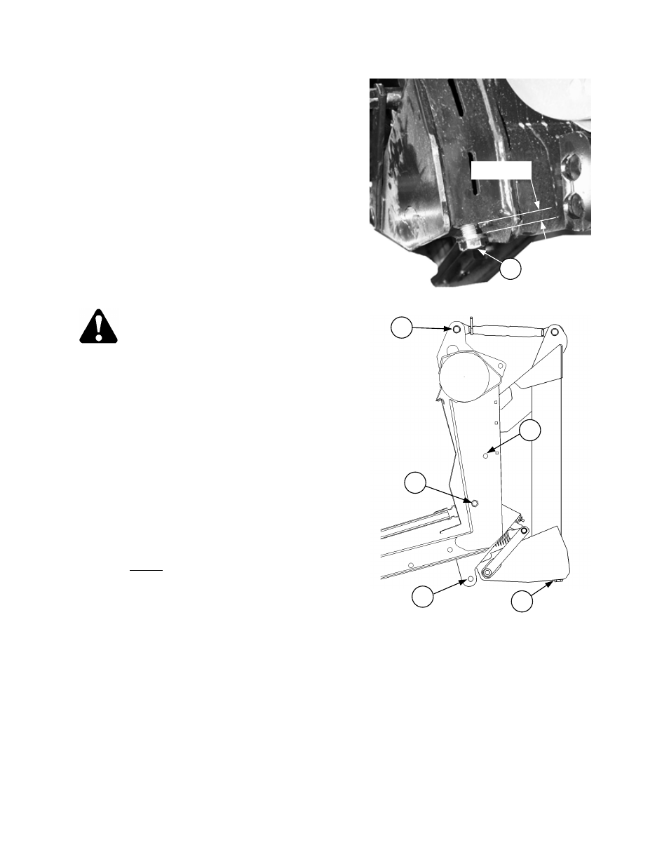
2. Back off bolt (B) until 1/2” (12 mm) thread is exposed.
This unloads tension on the leaf springs. Repeat at
other side of adapter.
3. Lower jack stand at left header leg.
4. Disengage feeder house cylinder stops and lower
header to the ground. Raise reel to maximum height.
Stop engine.
5. Engage reel props. Disconnect all hydraulic lines, wiring
harness, and driveline to isolate header from adapter
and combine. (Remove plastic wear strip from feed pan
if necessary.)
6. Remove 3/4 x 7-1/2” bolts (D) which lock adapter into
header. Do not lock out float by installing any pin at
position (C). Store the float lock-out pins at (E).
7. Raise header enough to position 2x4 blocks (40 mm)
under cutterbar at outward sides of adapter.
8. Lower header onto blocks. Remove center link pin (F).
It may be necessary to rotate link to allow removal.
B
D
C
F
E
B
½” (12 mm)