MacDon 872 Combine Adapter User Manual
Page 38
38
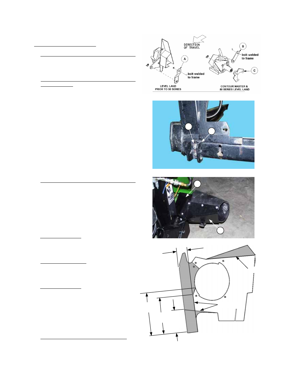
INSTALL PUMP TORQUE ARM SUPPORT
Adapter Mounting Instructions
for John Deere Combines
PREPARING THE ADAPTER
1. Level Land Prior to 50 series Feeder House:
Install pump torque arm support (A) to bolt
welded to R/H frame member of adapter using
3/4” locknut at (K). Orient support as shown.
Contour Master and 50 series Level Land
Feeder House: Install pump torque arm
support (B) to bolt welded to R/H frame
member of adapter using 3/4” locknut at (L).
Orient support as shown.
NOTE: For 9650 Combine, bolt torque arm (C)
(with two bends) to existing torque arm using
three M12 x 30 bolts.
2. Attach locking channels (H) to adapter frame,
using locking bar (J) between channel and lock
nuts. Install channels with single-hole leg
outboard and narrower clearance to bottom on
two-hole leg as shown.
NOTE: Lock pins at bottom of combine feeder
house engage these channels. Adjust position
of channels (H) by loosening hardware and
sliding channels up and down for proper
alignment.
3. Level Land Prior to 50 series Feeder House:
Attach shield (D) to left side of adapter frame
with 5/16 x 3/4” flange bolt and nut.
NOTE: Install nut “upside down”, that is, with
serrated flange down, so flats of hex engage in
slot in adapter frame.
NOTE: For 9600 and 8820 combines, shield
(G) is not required. Remove prior to installation
of shield (D). Swing shield (D) forward for end
transport situations.
4. Contour Master only: Add float range limiters to
prevent damage to the retracting tine drum
and/or header side drapers when operating at
flat header angles. See instruction on page 71.
5. Contour Master only: Trim plastic closure
panels as shown at right (shaded area). Leave
panels off of adapter until just before adapter is
completely installed in header.
6. Contour Master only: Move retracting tine drum
forward from the factory installed position to as
shown on page 34. NOTE: To avoid damage
to the tine drum and/or combine, leave drum
mounting hardware loose until the
combine/adapter/header package is fully
together. Adjust center link (connecting header
to adapter) to minimum length, float header up,
then tighten drum mounting hardware.
7. 9500/10,CTS/II, STS and CTS 50 Series: To
avoid damage to header, remove one tine from
each end of retracting tine drum.
INSTALL LOCKING CHANNELS
H
J
ATTACH L/H SHIELD: LEVEL LAND
G
D
TRIM PLASTIC PANELS
CONTOUR MASTER ONLY
Trim Line
Trim Line
190 mm
(7-1/2”)
325 mm
(12-3/4”)
370 mm
(14-1/2”)
95 mm
(3-3/4”)