Unloading & assembly – MacDon 974 FlexDraper User Manual
Page 86
Form # 147083
Issue 01/07
84
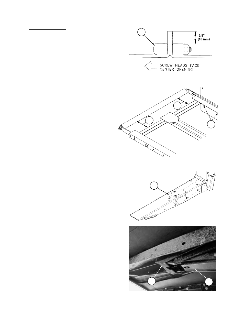
FIXED ROLLER ALIGNMENT
A
B
C
D
UNLOADING & ASSEMBLY
INSTALL DRAPERS (continued)
3. Connect draper with screw heads (S) facing
center opening.
NOTE: Place connector tube so holes closest
to end of tube are at the cutterbar.
4. Ensure V-guide on underside of draper
engages grooves at rear of both rollers.
5. Check draper to cutterbar clearance. Maximum
gap is 1 mm. If adjustment is required, see
“Deck Height” on page 55.
6. Apply draper tension until white indicator bar is
partially hidden behind roller support arm. See
"Draper Tension Adjustment" in Maintenance
/Service section of Operator's Manual.
7. Position decks to dimension (X) (see chart on
previous page) for desired opening width. The
recommended starting position is with decks
shifted in. See "-Delivery Opening Width" in
Operation section of Operator's Manual.
8. Align idler rollers for proper draper tracking.
Align roller by loosening two bolts in rear
support (C) and adjusting in slots until
dimensions (A) and (B) are:
21’ & 25’ Headers – equal front and rear.
30’, 36’ & 39’ Headers – Dimension (B) 3 mm
(1/8”) less than Dimension (A).
See page 54 for details.
9. Cut excessive flap off of draper, leaving 3/8"
(10 mm) extending above the connector. Trim
the new ends at the front corners as shown on
page 82. This allows draper to fit properly
under front draper seal to prevent tearing of
front edge. Use the cut-offs as a guide for
trimming. Keep the cut-offs for use as a splice.
INSTALL LINKAGE SUPPORTS (973 Only)
Attach linkage supports (D) to header lower legs,
using two 3/8 x 3/4” Torx Head screws per side.
IMPORTANT: When attaching header to adapter,
adapter leg (E) must engage header leg on top of
support (D) as shown, both sides.
CONNECTOR SCREW HEADS
S
SUPPORTS IN LOWER LEGS: 973 ONLY
D
E